
Owner's manual


Chapter 4 Signal Connections
National Instruments Corporation 4-5 DAQCard E Series User Manual
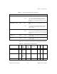
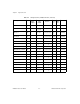
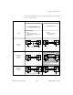
Table 4-2 shows the I/O signal summary for the DAQCard-AI-16E-4.
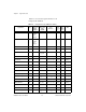
PFI7/STARTSCAN
DGND Input
Output
PFI7/Start of Scan—As an input, this is one of the PFIs.
As an output, this is the STARTSCAN signal. This pin
pulses once at the start of each analog input scan in the
interval scan. A low-to-high transition indicates the start of
the scan.
PFI8/GPCTR0_SOURCE DGND Input
Output
PFI8/Counter 0 Source—As an input, this is one of the
PFIs.
As an output, this is the GPCTR0_SOURCE signal. This
signal reflects the actual source connected to general-
purpose counter 0.
PFI9/GPCTR0_GATE DGND Input
Output
PFI9/Counter 0 Gate—As an input, this is one of the PFIs.
As an output, this is the GPCTR0_GATE signal. This signal
reflects the actual gate signal connected to general-purpose
counter 0.
GPCTR0_OUT DGND Output Counter 0 Output—This output is from the general-purpose
counter 0 output.
FREQ_OUT DGND Output Frequency Output—This output is from the frequency
generator output.
Table 4-2.
I/O Signal Summary, DAQCard-AI-16E-4
Signal Name
Drive Impedance
Input/
Output
Protection
(Volts)
On/Off
Source
(mA at V)
Sink
(mA at
V)
Rise
Time
(ns)
Bias
ACH<0..15>
AI 100 G
Ω
in parallel
with
100 pF
25/10 — — —
±
200 pA
AISENSE AI 100 G
Ω
in parallel
with
100 pF
25/10 — — —
±
200 pA
AIGND AI — — — — — —
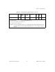
Table 4-1.
I/O Connector Signal Descriptions (Continued)
Signal Name
Reference Direction Description