
Owner's manual

Chapter 4 Signal Connections
National Instruments Corporation 4-41 DAQCard E Series User Manual
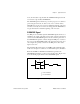
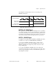
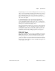
Figure 4-28 shows the timing requirements for the GPCTR1_GATE
signal.
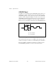
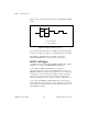
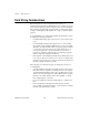
GPCTR1_OUT Signal
This signal is available only as an output on the GPCTR1_OUT pin.
The GPCTR1_OUT signal monitors the TC board general-purpose
counter 1. You have two software-selectable output options—pulse on
TC and toggle output polarity on TC. The output polarity is software
selectable for both options. This signal is set to input (High-Z) at
startup. Figure 4-29 shows the timing requirements for the
GPCTR1_OUT signal.
Figure 4-28.
GPCTR1_GATE Signal Timing in Edge-Detection Mode
Figure 4-29.
GPCTR1_OUT Signal Timing
Rising-edge
polarity
Falling-edge
polarity
t
w
t
w
= 10 ns minimum
GPCTR1_SOURCE
GPCTR1_OUT
GPCTR1_OUT
(Toggle output on TC)
(Pulse on TC)
TC