
Network Card User Manual

© National Instruments Corp. 7 FP-1600
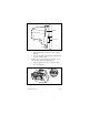
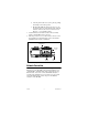
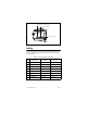
Figure 7.
FP-1600 Power Connector Pinout
Connect the primary power supply to the center V and C pair.
You can connect an optional backup power supply to the left V
and C pair. The right V and C pair provides a convenient means
of connecting power to the V and C terminals of a terminal base.
Figure 7 shows this optional connection.
Specifications
Network interface .............................10BaseT and 100BaseTX
Ethernet
Compatibility....................................IEEE 802.3
Communications rate........................10 Mbps, 100 Mbps,
autonegotiated
Cabling distance................................100 m
Power supply range...........................11 to 30 VDC
Power consumption...........................7 W + 1.15
*
∑
(I/O module
power requirements
)
Maximum terminal bases per bank...9
Maximum number of banks..............determined by network
topology
Operating temperature ......................–40 to +55 °C
Storage temperature..........................–55 to +85 °C
Relative humidity..............................5% to 90% non-condensing
Weight...............................................250 g (8.7 oz.)
v
v
v
c
c
c
11-30 VDC
Backup Power
Supply
(optional)
+
–
+
–
11-30 VDC
Primary Power
Supply
V
C
To adjacent device
(optional connection)