FIELDPOINT ™ OPERATING INSTRUCTIONS AND SPECIFICATIONS FP-PWM-520 and cFP-PWM-520 Eight-Channel, 5 V or 10–30 V PWM Output Module These operating instructions describe how to install and use the National Instruments FP-PWM-520 and cFP-PWM-520 pulse-width modulation modules (referred to inclusively as the [c]FP-PWM-520). For details on configuring and accessing the [c]FP-PWM-520 over a network, refer to the user manual for the FieldPoint network module you are using.
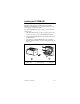
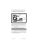
Installing the FP-PWM-520 The FP-PWM-520 mounts on a FieldPoint terminal base (FP-TB-x), which provides operating power to the module. Installing the FP-PWM-520 onto a powered terminal base does not disrupt the operation of the bank. To install the FP-PWM-520, refer to Figure 1 and complete the following steps: 1. Slide the terminal base key to either position X, used for any module, or position 4, used for the FP-PWM-520 module. 2.
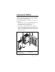
Installing the cFP-PWM-520 The cFP-PWM-520 mounts on a Compact FieldPoint backplane (cFP-BP-x or cFP-180x), which provides operating power to the module. Installing the cFP-PWM-520 onto a powered backplane does not disrupt the operation of the bank. To install the cFP-PWM-520, refer to Figure 2 and complete the following steps: 1. Align the captive screws on the cFP-PWM-520 with the screw holes on the backplane. The alignment keys on the cFP-PWM-520 prevent backward insertion. 2.
Wiring the [c]FP-PWM-520 The FP-TB-x terminal base has connections for each of the eight output channels and for an external power supply to power the output channels and field devices. The cFP-CB-x connector block provides the same connections. Each channel has one output terminal (VOUT ), one supply terminal (VSUP), and two common terminals (COM). All eight channels are referenced to the COM terminals. The V and VSUP terminals are all internally connected, as are the C and COM terminals.
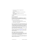
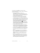
Install a 2 A maximum, fast-acting fuse between the external power supply and the VSUP terminal on each channel. Install a 1 A maximum, fast-acting fuse suitable for the load at the VOUT terminal. Figure 3 shows fuses where appropriate. C V VSUP Protected Sourcing Output 2 A Max User-Supplied Fuse 1 A Max User-Supplied Fuse VOUT 5 VDC or 10–30 VDC External – Power Supply + Load COM COM [c]FP-PWM-520 Figure 3.
In the ON state, the effective resistance between VOUT and VSUP causes a voltage drop between the external supply voltage and the output voltage. For example, if the external supply voltage is 5 V and the output current is 1 A, calculate the output voltage as follows: 5 V – (1 A × RON) = VOUT where RON is the ON resistance and VOUT is the output voltage. Refer to the Specifications section for the value of the ON resistance.
• Disconnect the external power supply from the [c]FP-PWM-520. • Remove the [c]FP-PWM-520 from the terminal base or backplane. • Power off the network module connected to the [c]FP-PWM-520. Normal operation can resume after you correct the short-circuit condition. Overcurrent Protection Each output channel on the [c]FP-PWM-520 has circuitry that protects it from current surges resulting from short circuits.
Configuring the Output Channels A [c]FP-PWM-520 output channel uses period and duty-cycle settings to determine when the channel is on or off. To configure the period, complete the following steps in Measurement & Automation Explorer (MAX): 1. On the Channel Configuration tab for the [c]FP-PWM-520, select Period from the Attribute menu. 2. Enter an integer between 1 ms (1 kHz) and 65,535 ms (0.01525 Hz) in the Value field.
[c]FP-PWM-520, it sends initial configuration information to the [c]FP-PWM-520. After the [c]FP-PWM-520 receives this initial information, the green READY indicator lights and the module is in normal operating mode. In addition to the green POWER and READY indicators, each channel has a numbered, green status LED that lights when the channel is in the ON state. Upgrading Your FieldPoint Firmware You may need to upgrade your FieldPoint firmware when you add new I/O modules to your FieldPoint system.
Even though the [c]FP-PWM-520 is designed to handle applications with hazardous potentials, follow these guidelines to ensure a safe total system: • There is no isolation between channels on the [c]FP-PWM-520. If a hazardous voltage is present on any channel, all channels are considered hazardous. Make sure that all other devices and circuits connected to the module are properly insulated from human contact.
Safety Guidelines for Hazardous Locations The cFP-PWM-520 is suitable for use in Class I, Division 2, Groups A, B, C, D, T4 hazardous locations; Class I, Zone 2, AEx nC IIC T4 and Ex nC IIC T4 hazardous locations; and nonhazardous locations only. Follow these guidelines if you are installing the cFP-PWM-520 in a potentially explosive environment. Failing to follow these guidelines may result in serious injury or death.
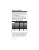
Specifications The following specifications are typical for a range of –40 to 70 °C unless otherwise noted. Output Characteristics Number of channels.......................... 8 Output type ....................................... Sourcing Output voltage .................................. Supply voltage – (Output current × Output impedance) Supply voltage ..................................
Guaranteed trip current Revision E and later modules..... 12.5 A Revision D and earlier modules ...................................... 20 A Trip time Revision E and later modules..... 10 μs at 13 A Behavior (revision E and later modules) Current Level Channel Behavior Module Protection 0–1 A Channel does not trip Module is not damaged 1–9 A Channel does not trip Module may be damaged 9–12.5 A Channel may trip Module may be damaged 12.
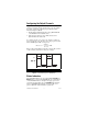
Mechanical Dimensions Figure 5 shows the mechanical dimensions of the FP-PWM-520 installed on a terminal base. If you are using the cFP-PWM-520, refer to your Compact FieldPoint controller user manual for the dimensions and cabling clearance requirements of the Compact FieldPoint system. 107.19 mm (4.22 in.) 109.5 mm (4.31 in.) 91.44 mm (3.60 in.) Figure 5. FP-PWM-520 Mechanical Dimensions Power Requirements Power from network module ............
Shock and Vibration These specifications apply only to the cFP-PWM-520. NI recommends Compact FieldPoint if your application is subject to shock and vibration. Operating vibration, random (IEC 60068-2-64).............................. 10–500 Hz, 5 grms Operating vibration, sinusoidal (IEC 60068-2-6)................................ 10–500 Hz, 5 g Operating shock (IEC 60068-2-27)..............................
Electromagnetic Compatibility This product is designed to meet the requirements of the following standards of EMC for electrical equipment for measurement, control, and laboratory use: • EN 61326 EMC requirements; Industrial Immunity • EN 55011 Emissions; Group 1, Class A • CE, C-Tick, ICES, and FCC Part 15 Emissions; Class A Note For EMC compliance, operate this device according to product documentation.
Waste Electrical and Electronic Equipment (WEEE) EU Customers At the end of their life cycle, all products must be sent to a WEEE recycling center. For more information about WEEE recycling centers and National Instruments WEEE initiatives, visit ni.com/ environment/weee.htm. ⬉ᄤֵᙃѻક∵ᶧࠊㅵ⧚ࡲ⊩ ˄Ё RoHS˅ Ёᅶ᠋ National Instruments ヺড়Ё⬉ᄤֵᙃ ѻકЁ䰤ࠊՓ⫼ᶤѯ᳝ᆇ⠽䋼ᣛҸ (RoHS)DŽ݇Ѣ National Instruments Ё RoHS ড়㾘ᗻֵᙃˈ䇋ⱏᔩ ni.com/environment/rohs_chinaDŽ (For information about China RoHS compliance, go to ni.
Where to Go for Support For more information about setting up the FieldPoint system, refer to these National Instruments documents: • FieldPoint network module user manual • Other FieldPoint I/O module operating instructions • FieldPoint terminal base and connector block operating instructions Go to ni.com/support for the most current manuals, examples, and troubleshooting information. For telephone support in the United States, create your service request at ni.
National Instruments, NI, ni.com, and LabVIEW are trademarks of National Instruments Corporation. Refer to the Terms of Use section on ni.com/legal for more information about National Instruments trademarks. Other product and company names mentioned herein are trademarks or trade names of their respective companies. For patents covering National Instruments products, refer to the appropriate location: Help»Patents in your software, the patents.txt file on your CD, or ni.com/patents.