GPIB-100A User Manual March 1990 Edition Part Number 320063-01 © Copyright 1985, 1991 National Instruments Corporation. All Rights Reserved.
National Instruments Corporation 6504 Bridge Point Parkway Austin, TX 78730-5039 (512) 794-0100 (800) IEEE-488 (toll-free U.S.
Limited Warranty The GPIB-100A is warranted against defects in materials and workmanship for a period of two years from the date of shipment, as evidenced by receipts or other documentation. National Instruments will, at its option, repair or replace equipment that proves to be defective during the warranty period. This warranty includes parts and labor.
FCC/DOC Radio Frequency Interference Compliance This equipment generates and uses radio frequency energy and, if not installed and used in strict accordance with the instructions in this manual, may cause interference to radio and television reception. This equipment has been tested and found to comply with (1) the limits for a Class A computing device, in accordance with the specifications in Subpart J of Part 15 of U.S.
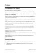
Preface Organization of the Manual This manual is divided into the following chapters: Chapter 1, Description of the GPIB-100A, contains a brief description of the GPIB-100A Bus Extender and how it is used. This section also lists all components and accessories. In addition, it provides system configuration, performance, operating, electrical, environmental, and physical specifications for the GPIB-100A.
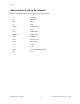
Preface Abbreviations Used in the Manual The following abbreviations are used in the text of this manual. C F centigrade Fahrenheit Hz hertz in.
Contents Chapter 1 Description of the GPIB-100A ....................................................................................... 1-1 Introduction...................................................................................................................... 1-1 GPIB-100A Specifications .............................................................................................. 1-3 Chapter 2 Installation..........................................................................................
Contents Appendix A Operation of the GPIB....................................................................................................... A-1 History of the GPIB......................................................................................................... A-1 Types of Messages .......................................................................................................... A-1 Talkers, Listeners, and Controllers.....................................................................
Contents Figures Figure 1-1. The Model GPIB-100A Bus Extender.................................................................. 1-1 Figure 1-2. Typical GPIB-100A Extension System (Physical Configuration) ........................ 1-2 Figure 1-3. Typical GPIB-100A Extension System (Logical Configuration).......................... 1-2 Figure 2-1. Voltage Selection.................................................................................................... 2-1 Figure 3-1.
Chapter 1 Description of the GPIB-100A Introduction The high-speed GPIB-100A Bus Extender (Figure 1-1) is used in pairs with a special parallel data transmission cable to connect two separate GPIB or IEEE-488 bus systems in a functionally transparent manner. Figure 1-1. The Model GPIB-100A Bus Extender While the two bus systems are physically separate, as shown in Figure 1-2, devices logically appear to be located on the same bus as shown in Figure 1-3.
Description of the GPIB-100A Chapter 1 extension. And because the GPIB-100A is a functionally transparent extender, the same GPIB communications and control programs that work with an unextended system will work unmodified with an extended system. There is one minor exception to this transparency in conducting parallel polls, as explained in Chapter 3 in the paragraph Parallel Poll Response (PPR) Modes.
Chapter 1 Description of the GPIB-100A GPIB-100A Specifications The following tables show the system configuration; the performance, operating, electrical, environmental, and physical characteristics of the GPIB-100A, as well as providing a list of available GPIB-100A components and accessories. Table 1-1.
Description of the GPIB-100A Chapter 1 Table 1-2. Performance Characteristics Characteristic Specification speed 250 to 135 kbytes/sec (approximately 4 µsec per byte degraded at 10.
Chapter 1 Description of the GPIB-100A Table 1-4.
Description of the GPIB-100A Chapter 1 Table 1-6. Physical Characteristics Characteristic Specification case style CS2 size 3.5 x 8.5 x 13 in. (89 x 216 x 330 mm) case material UL94V-0 flame retardant polystyrene Dow 60875 F or equivalent rack mounting single or dual kits available GPIB cable Hewlett Packard 10833 style or equivalent Transmission cable Dynatronics D-200-24 cable with AMP Amplimite connectors AMP HDP-20 50 pin connector with RFI/EMI shield Table 1-7.
Chapter 2 Installation Inspection Inspect the shipping container and contents for evidence of physical damage or stress. If damage is discovered and appears to have been caused in shipment, file a claim with the carrier. If the equipment is damaged, do not attempt to operate it before contacting National Instruments for instructions. Retain the shipping material for possible inspection by carrier or reshipment of the equipment.
Installation Chapter 2 Grounding Configuration A U.S. standard three-wire power cable is provided with the GPIB-100A. When connected to a power source, this cable connects the equipment chassis to the power ground. The GPIB-100A is shipped from the factory with chassis and power grounds connected to the logic ground of the digital circuitry and the shields of the interfacing cables.
Chapter 3 Configuration and Operation Users who are unfamiliar with the GPIB should first read Appendix A, Operation of the GPIB, to become familiar with GPIB terminology and protocol. In the following discussions, the terms local and remote refer to certain states of the two GPIB100A Bus Extenders in the system. When one extender is in a local state, meaning that the state in question originated on the local state's side, the other extender is in the corresponding remote state.
Configuration and Operation Chapter 3 Talker/Listener (TL) Mode There is no Controller and only one Talker in the TL mode of operation, sometimes called talk only mode. Usually, there is just one Listener as well. In the TL mode, the System and Active Controller states remain inactive and the IFC, REN, ATN, and SRQ signals are unused. The directions of the other signals are set the first time the Talker asserts DAV.
Chapter 3 Configuration and Operation Buffered PPR Mode (Approach 1) Most Controllers pulse the IDY signal for a period of time exceeding 2 µsec and expect a response within that time. When used with this type of Controller, the GPIB-100A should be left in the Buffered PPR mode as set at the factory. In this mode, the local GPIB-100A extender responds to IDY by outputting the contents of the PPR data register.
Configuration and Operation Chapter 3 Mixed Mode Operation If there are multiple Controllers and all of the same type are located on the same side of the extension, the two GPIB-100A units can be set to Unbuffered and Buffered PPR modes accordingly. BUF 1 2 3 O N 1 2 3 P P R O N P P R UNBUF A. Unbuffered PPR Mode B. Buffered PPR Mode represents the side of the switch you press down Figure 3-2.
Chapter 4 Theory of Operation Diagrams Figure 4-1 shows a block diagram for the GPIB-100A. Refer to Appendix B for GPIB-100A schematic diagrams and Appendix C for the GPIB-100A parts locator diagram. Figure 4-1. GPIB-100A Block Diagram Power-On When the GPIB-100A is powered on, a reset pulse (PON) created by U48F, U28A/D and associated Register/Capacitor Delay (RCD) network directly or indirectly clears all flip-flops (FFs) to an initialized state.
Theory of Operation Chapter 4 System Controller Detection PON initializes FFs U22A and U12A to clear the Remote System Controller (RSC) and Local System Controller (LSC) signals. When Interface Clear (IFC) is received from the local side via GPIB transceiver U2B, the LSC FF is set on the leading edge of IFC and after a delay through U21B/C/D/E, IFC is enabled (U35D) to the remote unit as XIFC through driver U29A.
Chapter 4 Theory of Operation • Whenever a change in the state of the local ATN signal is caused by a pulse created via U38E, U24B/C, and associated RC network. • While ATN or DAV is received from the local side (U34A/D). • During a parallel poll (U38F and U34A). Before the LS FF is set and unless a parallel poll is in progress, the unit drives the local Not Ready for Data (NRFD) signal passively false (U42C and U41C).
Theory of Operation Chapter 4 the remote poll response into register U16. Clearing U45B unasserts XEOI and XATN, and after they propagate to the remote side, BUS PP is also unasserted. This causes FF U36D to be cleared as well, terminating the parallel poll process and removing the NRFD condition of the local extender. To recap, FF U45B is set from the start of the local poll until the remote response is available and the local poll is over.
Appendix A Operation of the GPIB History of the GPIB The GPIB is a link, bus, or interface system through which interconnected electronic devices communicate. Hewlett-Packard invented the GPIB, which they call the HP-IB, to connect and control programmable instruments manufactured by them. Because of its high system data rate ceilings of from 250 kbytes/sec to 1 Mbytes/sec per second, the GPIB quickly became popular in other applications such as intercomputer communication and peripheral control.
Operation of the GPIB Appendix A The role of the GPIB Controller can also be compared to the role of the computer's CPU, but a better analogy is to the switching center of a city telephone system. The switching center (Controller) monitors the communications network (GPIB). When the center (Controller) notices that a party (device) wants to make a call (send a data message), it connects the caller (Talker) to the receiver (Listener).
Appendix A Operation of the GPIB Figure A-1 shows the arrangement of these signals on the GPIB cable connector. 1 2 3 4 5 6 7 8 9 10 11 12 DIO1* DIO2* DIO3* DIO4* EOI* DAV* NRFD* NDAC* IFC* SRQ* ATN* SHIELD 13 14 15 16 17 18 19 20 21 22 23 24 DIO5* DIO6* DIO7* DIO8* REN* GND (TW PAIR W/DAV*) GND (TW PAIR W/NRFD*) GND (TW PAIR W/NDAC*) GND (TW PAIR W/IFC*) GND (TW PAIR W/SRQ*) GND (TW PAIR W/ATN*) SIGNAL GROUND Figure A-1.
Operation of the GPIB Appendix A NDAC (not data accepted) NDAC indicates when a device has or has not accepted a message byte. The line is driven by all devices when receiving commands and by Listeners when receiving data messages. DAV (data valid) DAV tells when the signals on the data lines are stable (valid) and can be accepted safely by devices. The Controller drives DAV when sending commands, and the Talker drives it when sending data messages.
Appendix A Operation of the GPIB Physical and Electrical Characteristics Devices are usually connected with a cable assembly consisting of a shielded 24-conductor cable with both a plug and receptacle at each end. This design allows devices to be connected in either a linear or a star configuration, or a combination of the two. See Figures A-2 and A-3. Figure A-2.
Operation of the GPIB Appendix A Figure A-3. Star Configuration of GPIB Devices The standard connector is the Amphenol or Cinch Series 57 MICRORIBBON or AMP CHAMP type. An adapter cable using non-standard cable and/or connector is used for special interconnect applications. The GPIB uses negative logic with standard TTL logic levels. When DAV is true, for example, it is a TTL low level (≤ 0.8 V), and when DAV is false, it is a TTL high level (≥ 2.0 V).
Appendix A Operation of the GPIB Configuration Restrictions To achieve the high data transfer rate that the GPIB is designed for, the physical distance between devices and the number of devices on the bus is limited. The following restrictions are typical: • A maximum separation of 4 m between any two devices and an average separation of 2 m over the entire bus. • A maximum total cable length of 20 m. • No more than 15 devices connected to each bus, with at least two-thirds powered-on.
Appendix B Schematic Diagram This appendix contains the schematic diagram for the GPIB-100A.
Appendix C GPIB-100A Parts Locator Diagram This appendix contains the parts locator diagram for the GPIB-100A. The parts locator diagram shows the locations of the GPIB-100A configuration jumpers and switches. Figure C-1.
Appendix D Cable Assembly Wire List This appendix contains the wire list for the GPIB-100A Transmission Cable.
Table D-1.
Appendix E Multiline Interface Command Messages The following tables are multiline interface messages (sent and received with ATN TRUE).
Multiline Interface Command Messages Appendix E Multiline Interface Messages Hex Oct Dec ASCII Msg 00 01 02 03 04 05 06 07 000 001 002 003 004 005 006 007 0 1 2 3 4 5 6 7 08 09 0A 0B 0C 0D 0E 0F 010 011 012 013 014 015 016 017 8 9 10 11 12 13 14 15 BS HT LF VT FF CR SO SI 10 11 12 13 14 15 16 17 020 021 022 023 024 025 026 027 16 17 18 19 20 21 22 23 DLE DC1 DC2 DC3 DC4 NAK SYN ETB 18 19 1A 1B 1C 1D 1E 1F 030 031 032 033 034 035 036 037 24 25 26 27 28 29 30 31 CAN EM SUB ESC FS GS RS US
Appendix E Multiline Interface Command Messages Multiline Interface Messages Hex Oct 40 41 42 43 44 45 46 47 100 101 102 103 104 105 106 107 64 65 66 67 68 69 70 71 48 49 4A 4B 4C 4D 4E 4F 110 111 112 113 114 115 116 117 50 51 52 53 54 55 56 57 58 59 5A 5B 5C 5D 5E 5F PPE PPU SDC SPD Dec ASCII Msg Hex Oct @ A B C D E F G MTA0 MTA1 MTA2 MTA3 MTA4 MTA5 MTA6 MTA7 60 61 62 63 64 65 66 67 140 141 142 143 144 145 146 147 96 97 98 99 100 101 102 103 ` a b c d e f g MSA0,PPE MSA1,PPE MSA2,PPE M
Appendix F Mnemonics Key This appendix contains a mnemonics key that defines the mnemonics (abbreviations) used throughout this manual.
Mnemonics Key Appendix F Mnemonic Definition REN Remote Enable RFD Ready for Data RR Remote Response RS Remote Source RSC Remote System Controller SRQ Service Request T Talker TL Talker/Listener TLC Talker/Listener/Controller (GPIB Adapter) TTL Transistor/Transistor Logic GPIB-100A User Manual F-2 © National Instruments Corporation
User Comment Form National Instruments encourages you to comment on the documentation supplied with our products. This information helps us provide quality products to meet your needs. Title: GPIB-100A User Manual Edition Date March 1990 Part Number: 320063-01 Please comment on the completeness, clarity, and organization of the manual. If you find errors in the manual, please record the page numbers and describe the errors. Thank you for your help.