
User manual


© National Instruments Corporation 23 NI High-Speed Digitizers Getting Started Guide
Table 7 describes the signal connections for the NI PXI-5102.
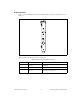
Figure 19 shows the pin assignments for the 9-pin DIN connector on the NI PXI-5102.
Figure 19. 9-Pin DIN Connector for NI PXI-5102, NI PXI/PCI-5112, and NI PCI-5911
Note The +5 V signal is fused at 1.1 A. However, NI recommends limiting the current from this pin
to 30 mA. The fuse is self-resetting.
Table 7. NI PXI-5102 Front Panel Signal Connections
Connector Description Function
CH 0,
CH 1
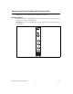
Standard BNC female
connector
Analog input connection; digitizes data and triggers
acquisitions.
TRIG Standard BNC female
connector
External analog trigger connection; signals on the TRIG
connector cannot be digitized.
PFI 1 Standard SMB jack
connector
Multipurpose digital timing and triggering signal.
AUX 9-pin mini-circular DIN
connector
Access to PFI 2 (with optional cable). For pinout information,
refer to Figure 19.
1 +5 V (Fused)
2GND
3 Reserved
4 Reserved
5 Reserved
6PFI 2
7 Reserved
8 Reserved
9 Reserved
4
3
5
6
7
8
9
1
2