Motion Control NI 7350 User Manual NI 7350 User Manual July 2006 371060B-01
Support Worldwide Technical Support and Product Information ni.
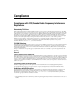
Important Information Warranty The National Instruments PXI/PCI-7350 is warranted against defects in materials and workmanship for a period of one year from the date of shipment, as evidenced by receipts or other documentation. National Instruments will, at its option, repair or replace equipment that proves to be defective during the warranty period. This warranty includes parts and labor.
Compliance Compliance with FCC/Canada Radio Frequency Interference Regulations Determining FCC Class The Federal Communications Commission (FCC) has rules to protect wireless communications from interference. The FCC places digital electronics into two classes. These classes are known as Class A (for use in industrial-commercial locations only) or Class B (for use in residential or commercial locations). All National Instruments (NI) products are FCC Class A products.
Contents About This Manual Conventions ...................................................................................................................ix Related Documentation..................................................................................................x Chapter 1 Introduction About the NI 7350 Controller ........................................................................................1-1 Features.................................................................................
Contents Onboard Sinusoidal Commutation.................................................................. 4-3 Flash Memory ................................................................................................. 4-3 Axes and Motion Resources.......................................................................................... 4-3 Axes ................................................................................................................ 4-3 Motion Resources ...........................
Contents Appendix D Technical Support and Professional Services Glossary Index © National Instruments Corporation vii NI 7350 User Manual
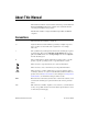
About This Manual This manual describes the electrical and mechanical aspects of the National Instruments PXI/PCI-7350 motion controller and contains information concerning its installation and operation. The NI 7350 controller is designed for PXI, CompactPCI, and PCI bus computers. Conventions This manual uses the following conventions: <> Angle brackets that contain numbers separated by an ellipsis represent a range of values associated with a bit or signal name—for example, AO <3..0>.
About This Manual monospace Text in this font denotes text or characters that you should enter from the keyboard, sections of code, programming examples, and syntax examples. This font is also used for the proper names of disk drives, paths, directories, programs, subprograms, subroutines, device names, functions, operations, variables, filenames, and extensions.
1 Introduction This chapter includes information about the features of the National Instruments PXI/PCI-7350 controller and information about operating the device. About the NI 7350 Controller The NI 7350 controller features advanced motion control with easy-to-use software tools and add-on motion VI libraries for use with LabVIEW. Features The NI 7350 controller is a combination servo and stepper motor controller for PXI, CompactPCI, and PCI bus computers.
Chapter 1 Introduction Hardware The NI 7350 controller is a high performance controller that uses an advanced dual-processor for embedded real-time control. This powerful functionality provides high-speed communications while off-loading complex motion functions from the host PC for maximum command throughput and system performance. The NI 7350 features motion profiles that are controlled with enhanced PID control loop/PIVff control loop high-speed servo update rates.
Chapter 1 Introduction ❑ One of the following software packages and documentation: – LabVIEW – LabWindows™/CVI™ – Measurement Studio – C/C++ – Microsoft Visual Basic ❑ A computer with an available PXI, CompactPCI, or PCI slot Software Programming Choices The NI 7350 controller comes with a simple but powerful high-level application programming interface (API) that makes it easy to program. You can execute all setup and motion control functions by calling into a dynamically-linked library (DLL).
Chapter 1 Introduction Optional Equipment National Instruments offers a variety of products for use with the NI 7350 controller, including the following accessories: • Cables and cable assemblies for motion and digital I/O • Universal Motion Interface (UMI) wiring connectivity blocks with integrated motion signal conditioning and motion inhibit functionality • Stepper and servo motor compatible drive amplifier units with integrated power supply and wiring connectivity • Connector blocks and shielde
Configuration and Installation 2 This chapter describes how to configure and install the National Instruments PXI/PCI-7350 controller. Software Installation Before installing the NI 7350 controller, install the NI-Motion software and, if appropriate, the NI-Motion VI libraries. For specific installation instructions, refer to Getting Started with NI-Motion for NI 73xx Motion Controllers, which is installed in the NI-Motion/Documentation folder where you installed NI-Motion.
Chapter 2 Configuration and Installation Safety Information The following section contains important safety information that you must follow when installing and using the NI 7350. Caution Do not operate the device in a manner not specified in this document. Misuse of the device can result in a hazard. You can compromise the safety protection built into the device if the device is damaged in any way. If the device is damaged, return it to National Instruments (NI) for repair.
Chapter 2 Configuration and Installation Remove power from signal lines before connecting them to or disconnecting them from the device. Operate the device at or below the measurement category1 marked on the hardware label. Measurement circuits are subjected to working voltages2 and transient stresses (overvoltage) from the circuit to which they are connected during measurement or test.
Chapter 2 Configuration and Installation Hardware Installation You can install the NI 7350 controller in any open compatible expansion slot in the computer. Appendix A, Specifications, lists the maximum power required for the NI 7350 controller. The following instructions are for general installation. Refer to the computer user manual or technical reference manual for specific instructions and warnings. The NI 7350 controller is a sensitive electronic device shipped in an antistatic bag.
Chapter 2 ♦ Configuration and Installation PCI-7350 1. Power off and unplug the computer. Caution To protect yourself and the computer from electrical hazards, the computer should remain unplugged until the installation is complete. 2. Open the computer case to expose access to the PCI expansion slots. 3. Choose an unused +3.3 V or +5 V PCI slot, and remove the corresponding expansion slot cover on the back panel of the computer. 4.
Chapter 2 Configuration and Installation software to work with this type of system, refer to the NI-Motion User Manual. When connecting to a drive that does not perform the sinusoidal commutation, the NI 7350 commutates the first two phases and the servo drive determines the third. Therefore, two DAC outputs are required per axis. Refer to the Measurement & Automation Explorer Help for Motion for information about configuring the NI-Motion software for brushless servo motors.
Chapter 2 Configuration and Installation Type 1 Base Case 0° 0° 0° 0° 0° 0° 180° 180° 180° 180° 180° 180° 360° 360° 360° 360° 360° 360° 540° 540° 540° 540° 540° 540° 720° Sensor 1 Input 1 Sensor 2 Input 2 Sensor 3 Input 3 720° Sensor 1 Input 1 Sensor 2 Input 2 Sensor 3 Input 3 720° Sensor 1 Input 1 Sensor 2 Input 2 Sensor 3 Input 3 720° Sensor 1 Input 1 Sensor 2 Input 2 Sensor 3 Input 3 720° Sensor 1 Input 1 Sensor 2 Input 2 Sensor 3 Input 3 720° Senso
Chapter 2 Configuration and Installation Type 2 Base Case 0° 0° 0° 0° 0° 0° 180° 180° 180° 180° 180° 180° 360° 360° 360° 360° 360° 360° 540° 540° 540° 540° 540° 540° 720° Sensor 1 Input 1 Sensor 2 Input 2 Sensor 3 Input 3 720° Sensor 1 Input 1 Sensor 2 Input 2 Sensor 3 Input 3 720° Sensor 1 Input 1 Sensor 2 Input 2 Sensor 3 Input 3 720° Sensor 1 Input 1 Sensor 2 Input 2 Sensor 3 Input 3 720° Sensor 1 Input 1 Sensor 2 Input 2 Sensor 3 Input 3 720° Senso
Chapter 2 Configuration and Installation For example, if the diagram supplied with the motor matches the third Type 2 diagram, wire Hall effect sensor 1 to input 3 on the UMI or NI 7350, and then wire sensor 2 to input 1 and wire sensor 3 to input 2. The Hall effect sensor inputs for Axes 1, 2, 5, and 6 are defined as follows: • Axis 1 uses digital port 4, bits 2–4, with bit 2 as input 1. • Axis 2 uses digital port 4, bits 5–7, with bit 5 as input 1.
Chapter 2 Configuration and Installation 0° 180° 360° 540° 720° 1 2 3 Figure 2-4. Type 2 Hall Sensor Phasing Sequence Diagram Refer to the Measurement & Automation Explorer Help for Motion for information about configuring the NI-Motion software for brushless servo motors. Connecting the Motor Leads For the brushless motor to generate maximum torque, the motion system must output the commutation on the three motor phases correctly.
Chapter 2 Configuration and Installation Table 2-1. Motor Phasing Diagram Motor Lead 0º 60º 120º 180º 240º 300º A + + NC – – NC B – NC + + NC – C NC – – NC + + 0° 60° 120° 180° 240° 300° A + NC C B – Figure 2-5. Sine Wave Motor Phasing Diagram Table 2-2 shows the correct method of wiring a brushless motor to the drive. Table 2-2.
3 Hardware Overview This chapter presents an overview of the National Instruments PXI/PCI-7350 controller hardware functionality. Figures 3-1 and 3-2 illustrate the functional components of the NI PXI-7350. 1 2 9 PXI-7350 3 8 7 1 2 3 4 5 16-bit ADC 16-bit DACs RTSI and PXI Bus Connector Field-Programmable Gate Arrays DSP 6 5 6 7 8 9 4 32-bit CPU Nonvolatile FLASH Memory 68-pin Digital I/O Connectors 68-pin Motion I/O Connectors Figure 3-1.
Chapter 3 Hardware Overview 1 c COPYRIGHT 2003 C 2 4 3 1 2 Assembly Number Label Serial Number Label 3 4 Symbol Indicating CE Compliance Identification Number (used in Australia) Figure 3-2. PXI-7350 Parts Locator Diagram (Back Panel) NI 7350 User Manual 3-2 ni.
Chapter 3 Hardware Overview Figures 3-3 and 3-4 show the NI PCI-7350 parts locator diagrams. 2 1 3 9 8 4 7 1 2 3 4 5 16-bit ADC 16-bit DACs RTSI Bus Connector Field-Programmable Gate Arrays DSP 6 5 6 7 8 9 32-bit CPU Nonvolatile FLASH Memory 68-pin Digital I/O Connectors 68-pin Motion I/O Connectors Figure 3-3.
Chapter 3 Hardware Overview 1 2 3 4 5 N114 Assy187109A 1 2 3 Symbol to Alert User to Read the Manual Identification Number (used in Australia) Symbol Indicating CE Compliance 4 5 Serial Number Label Assembly Number Label Figure 3-4.
Chapter 3 Hardware Overview 1 2 1 MOTION I/O (AXES 1-4) MOTION I/O (AXES 5-8) 3 DIGITAL I/O (PORTS 1-4) DIGITAL I/O (PORTS 5-8) Figure 3-5 shows the four 68-pin I/O connectors on the NI 7350 motion controller. Motion I/O Connector (Axes 1–4) Motion I/O Connector (Axes 5–8) 3 4 2 4 Digital I/O Connector (Ports 1–4) Digital I/O Connector (Ports 5–8) Figure 3-5.
4 Functional Overview This chapter provides an overview of the National Instruments PXI/PCI-7350 controller architecture and its capabilities. Dual Processor Architecture The NI 7350 controller can perform up to eight axes of simultaneous motion control in a preemptive, multitasking, real-time environment. An advanced dual-processor architecture, 32-bit CPU, digital signal processor (DSP) for embedded real-time control, and custom FPGAs give the NI 7350 controller high-performance capabilities.
Chapter 4 Functional Overview The DSP chip is a separate processor that operates independently from the CPU but is closely synchronized through interprocessor communication. The NI 7350 is a true multiprocessing and multitasking embedded controller. The architecture of the NI 7350 controller enables advanced motion features, such as enhanced PID functions and lowpass and notch filters. Refer to the Measurement & Automation Explorer Help for Motion for more information about these features.
Chapter 4 Functional Overview Onboard Sinusoidal Commutation The NI 7350 controller provides onboard sinusoidal commutation for axes controlling brushless DC servo motors. This feature reduces overall system cost by allowing you to use less complex, and therefore less expensive, motor drives. Flash Memory Nonvolatile memory on the NI 7350 controller is implemented with flash ROM, which means the controller can electrically erase and reprogram its own ROM.
Chapter 4 Functional Overview also require a feedback resource, while open-loop stepper axes do not. Figures 4-1 and 4-2 show these axis configurations. With the NI 7350 controller, you can map one or two feedback resources and one or two output resources to the axis. A stepper axis has its primary output resource mapped to a stepper output. A servo axis has its primary output resource mapped to a DAC.
Chapter 4 Functional Overview when implementing dual-loop control, such as in backlash compensation, which reduces the number of encoders available for other axes. Note Refer to the NI-Motion User Manual for more information about configuring axes. Motion Resources Encoder, DAC, ADC, and motion I/O resources that are not used by an axis are available for non-axis or non-motion-specific applications. You can directly control an unmapped DAC as a general-purpose analog output (±10 V).
Chapter 4 Functional Overview functions for up to 120 general-purpose variables. Refer to the NI-Motion User Manual for more information. The NI 7350 also features buffered operations for contouring, high-speed position captures, and breakpoints (position compare). You can store and run onboard programs and buffers from RAM or save them to flash ROM.
5 Signal Connections This chapter describes how to make input and output signal connections directly to the National Instruments PXI/PCI-7350 controller and briefly describes the associated I/O circuitry. The NI 7350 controller has the following four connectors that handle all signals to and from the external motion system.
Chapter 5 Signal Connections Figures 5-1 and 5-2 show the pin assignments for the two 68-pin motion I/O connectors on the NI 7350 controller. A signal description follows the connector pinout. In this chapter, lines above signal names indicate that the signal is active low.
Chapter 5 Axis 5 Dir (CCW) Digital Ground Digital Ground Axis 5 Home Switch Trigger 5 Axis 5 Inhibit Axis 6 Dir (CCW) Digital Ground Digital Ground Axis 6 Home Switch Trigger 6 Axis 6 Inhibit Axis 7 Dir (CCW) Digital Ground Digital Ground Axis 7 Home Switch Trigger 7 Axis 7 Inhibit Axis 8 Dir (CCW) Digital Ground Digital Ground Axis 8 Home Switch Trigger 8 Axis 8 Inhibit Digital Ground Breakpoint 5 Breakpoint 7 Digital Ground Analog Output 5 Analog Output 7 Analog Output Ground Analog Input 5 Analog Input
Chapter 5 Signal Connections Table 5-1 describes the signals on the motion I/O connector. Table 5-1. Motion I/O Signal Connections Signal Name Reference Direction — — Axis <1..8> Dir (CCW) Digital Ground Output Motor direction or counterclockwise control Axis <1..8> Step (CW) Digital Ground Output Motor step or clockwise control Axis <1..8> Encoder Phase A Digital Ground Input Closed-loop only—phase A encoder input Axis <1..
Chapter 5 Signal Connections Motion Axis Signals The following signals control the servo amplifier or stepper drive. • Analog Output <1..8>—These 16-bit DAC outputs are typically the servo command outputs for each axis. They can drive the industry-standard ±10 V output, and can be software limited to any positive or negative voltage range desired. These outputs also feature a software-programmable voltage offset.
Chapter 5 Signal Connections You can choose to drive the Step (CW) and Dir (CCW) outputs by using either Totem Pole mode or Open Collector mode. In Totem Pole mode, the output buffer can both sink and source current, which is appropriate for most applications. In Open Collector mode, the output buffer can only sink current. By default, Step (CW) and Dir (CCW) outputs are set to Totem Pole mode. Caution Do not connect these outputs to anything other than a +5 V circuit.
Chapter 5 Signal Connections Limit and home inputs are digitally filtered and must remain active for at least 1 ms to be recognized. Refer to Appendix A, Specifications, for more information. You can use MAX to disable digital filtering for limit and home inputs. Active signals should remain active to prevent motion from proceeding further into the limit. Pulsed limit signals stop motion, but they do not prevent further motion in that direction if another move is started.
Chapter 5 Signal Connections Caution Excessive input voltages can cause erroneous operation and/or component failure. Verify that the input voltage is within the specification range. Encoder Signals The NI 7350 controller offers up to eight channels of single-ended quadrature encoder inputs. All National Instruments power drives and UMI accessories provide built-in circuitry that converts differential encoder signals to single-ended encoder signals.
Chapter 5 Signal Connections measure—inch, centimeter, millimeter, and so on. For example, a 500 line encoder has 2,000 quadrature counts per revolution. Axis <1..8> Encoder Index The Index input is primarily used to establish a reference position. This function uses the number of counts per revolution or the linear distance to initiate a search move that locates the index position.
Chapter 5 Signal Connections Wire encoder signals and their ground connections separately from all other connections. Wiring these signals near the motor drive/amplifier or other signals can cause positioning errors and faulty operation. Caution National Instruments strongly recommends you use encoders with differential line drive outputs for all applications. You must use differential encoders if the encoder cable length is longer than 3.05 m (10 ft).
Chapter 5 Signal Connections The polarity of the trigger (position capture) input is programmable in software as active low, or active high, rising edge or falling edge. You also can use a trigger (position capture) input as a latching general-purpose digital input by simply ignoring the captured position.
Chapter 5 Signal Connections Trigger Input and Shutdown Input Circuits Trigger (position capture) input and shutdown input circuits have onboard pull-up resistors, and are interpreted as high logic level if left floating. Analog Inputs The NI 7350 controller has the following ADC input signals: • Analog Input <1..8>—The NI 7350 controller includes an eight-channel multiplexed, 16-bit ADC capable of measuring ±10 V, ±5 V, 0–10 V, and 0–5 V inputs.
Chapter 5 Signal Connections Wiring Concerns For proper use of each ADC input channel, the analog signal should be a floating source with the positive terminal connected to the channel input and the negative terminal connected to analog input ground. Figure 5-4 shows a simplified schematic diagram of this connection. Analog Input + – Vs Analog Input Ground + – Figure 5-4.
Chapter 5 Signal Connections 7350 or UMI Drive +5 3.3 kΩ STEP OUT Optional Step + Step – GND Figure 5-5. Typical Optocoupler Wiring (Totem Pole Output Mode) In some rare circumstances, the optocoupler will not work with a 5 V signal, or it requires more current than the maximum current level the controller can provide.
Chapter 5 Signal Connections Digital I/O Connector The general-purpose digital I/O lines on the NI 7350 controller are available on two separate 68-pin digital I/O connectors. Figures 5-7 and 5-8 show the pin assignments for these connectors.
Chapter 5 Signal Connections +5 V Reserved Reserved Reserved Reserved Reserved Reserved Reserved Reserved Port 5:bit 0 Digital Ground Port 5:bit 3 Port 5:bit 4 Digital Ground Port 5:bit 7 Port 6:bit 0 Port 6:bit 1 Digital Ground Digital Ground Digital Ground Port 6:bit 6 Port 6:bit 7 Port 7:bit 0 Digital Ground Port 7:bit 3 Port 7:bit 4 Digital Ground Port 7:bit 7 Port 8:bit 0 Digital Ground Axis 3, Hall 2/Port 8:bit 3 Axis 3, Hall 3/Port 8:bit 4 Digital Ground Axis 4, Hall 3/Port 8:bit 7 1 2 3 4 5 6 7 8
Chapter 5 Signal Connections Bits 2–7 in DIO ports 4 and 8 are dual-purpose bits that can be used for either general-purpose I/O or Hall sensor feedback during system configuration and initialization, but not both. When you set these bits to provide Hall sensor feedback, they are reserved for this activity and cannot be used for general-purpose I/O until you reinitialize the motion system. All digital I/O lines have programmable direction and polarity.
Chapter 5 Signal Connections RTSI Connector The PXI-7350 uses the PXI chassis backplane to connect to other RTSI-capable devices. The PCI-7350 uses a ribbon cable to connect to other RTSI-capable PCI devices. RTSI Signal Considerations The NI 7350 controller allows you to use up to eight RTSI trigger lines as sources for trigger inputs, or as destinations for breakpoint (position compare) outputs and encoder signals. The RTSI trigger lines also can serve as a generic digital I/O port.
A Specifications This appendix lists the hardware and software performance specifications for the PXI/PCI-7350 controller. Hardware specifications are typical at 25 °C, unless otherwise stated. Servo Performance PID update rate range............................. 62.5µs/sample to 5 ms/sample Max PID update rate ....................... 62.5 µs per 2 axes 8-axis PID update rate..................... 250 µs total Trajectory update rate ............................
Appendix A Specifications Servo control loop modes .......................PID, PIVff, S-Curve, Dual Loop PID (Kp, Ki, and Kd) gains .............0 to 32,767 Integration limit (Ilim).....................0 to 32,767 Derivative sample period (Td).........1 to 63 samples Feedforward (Aff, Vff) gains ..........0 to 32,767 Velocity feedback (Kv) gain ...........0 to 32,767 Servo command analog outputs Voltage range...................................±10 V Resolution........................................
Appendix A Specifications S-curve time range .......................... 1 to 32,767 samples Following error range ..................... 0 to 32,767 counts Gear ratio ........................................ ±32,767:1 to ±1:32,767 Stepper outputs Max pulse rate................................. 8 MHz (full, half, and microstep) Max pulse width.............................. 6.5 μs at <40 kHz Min pulse width .............................. 40 ns at >4 MHz Step output mode ............................
Appendix A Specifications Min pulse width...............................Programmable; depends on digital filter settings Voltage range...................................0 to 5 V Input low voltage......................0.8 V Input high voltage.....................2 V Built-in pull-up resistor ...................3.3 kΩ to +5 V Min index pulse width .....................Programmable; depends on digital filter settings Forward, reverse, and home inputs Number of inputs.............................
Appendix A Specifications Max buffered capture rate1 ............. 2 kHz per axis Breakpoint (position compare) outputs Number of outputs .......................... Up to 8 (Encoders 1 through 8) Voltage range .................................. 0 to 5 V Output low voltage .................. 0.6 V at 64 mA sink Output high voltage ................. Totem Pole: 2 V at 16 mA source; open collector: built-in 3.3 kΩ pull-up to +5 V Polarity............................................
Appendix A Specifications Input coupling..................................DC Input impedance ..............................100 MΩ min Voltage range (programmable)........±10 V, ±5 V, 0–10 V, 0–5 V Bandwidth........................................234 kHz Resolution........................................16 bits, no missing codes Monotonicity ...................................Guaranteed Absolute accuracy all ranges..........................................0.5% of full-scale System noise ±10 V .............
Appendix A Specifications Digital I/O Ports ....................................................... Up to 8 8-bit ports Line direction .................................. Individual bit programmable Inputs Voltage range .................................. 0 to 5 V Input low voltage ..................... 0.8 V Input high voltage .................... 2.0 V Polarity............................................ Programmable, active high or active low Built-in pull-up resistor..........................
Appendix A Specifications Maximum Power Requirements +3.3 V (±10%)........................................2 A +5 V (±5%).............................................2 A +12 V (±5%)...........................................30 mA –12 V (±10%) .........................................0 mA Power consumption ................................18 W Physical Dimensions (Not Including Connectors) PXI-7350 ................................................16 cm × 10 cm (6.3 in. × 3.9 in.) PCI-7330....................
Appendix A Specifications Maximum Working Voltage Channel-to-earth..................................... 11 V, Installation Category I (signal voltage plus common-mode voltage) Channel-to-channel ................................ 22 V, Installation Category I (signal voltage plus common-mode voltage) These values represent the maximum allowable voltage between any accessible signals on the controller.
Appendix A Specifications Electromagnetic Compatibility This product is designed to meet the requirements of the following standards of EMC for electrical equipment for measurement, control, and laboratory use: Note • EN 61326 EMC requirements; Minimum Immunity • EN 55011 Emissions; Group 1, Class A • CE, C-Tick, ICES, and FCC Part 15 Emissions; Class A For EMC compliance, operate this device according to product documentation.
B Cable Connector Descriptions This appendix describes the connector pinout for the cables that connect to the PXI/PCI-7350 controller. Figures B-1 and B-2 show the pin assignments for the stepper 50-pin motion connectors, while Figures B-3 and B-4 show the pin assignments for the servo 50-pin motion connectors. These connectors are available when you use the SH68-C68-S shielded cable assembly and the 68M-50F step/servo bulkhead cable adapter. You can order the cable assembly and cable adapter from ni.
Appendix B Cable Connector Descriptions Axis 1 Dir (CCW) Digital Ground Digital Ground Axis 1 Home Switch Trigger/Breakpoint 1 Axis 1 Inhibit Axis 2 Dir (CCW) Digital Ground Digital Ground Axis 2 Home Switch Trigger/Breakpoint 2 Axis 2 Inhibit Axis 3 Dir (CCW) Digital Ground Digital Ground Axis 3 Home Switch Trigger/Breakpoint 3 Axis 3 Inhibit Axis 4 Dir (CCW) Digital Ground Digital Ground Axis 4 Home Switch Trigger/Breakpoint 4 Axis 4 Inhibit Digital Ground 1 3 5 7 9 11 13 15 17 19 21 23 25 27 29 31 33
Appendix B Cable Connector Descriptions Axis 5 Dir (CCW) 1 2 Axis 5 Step (CW) Digital Ground 3 4 Axis 5 Encoder Phase A Digital Ground 5 6 Axis 5 Encoder Phase B Axis 5 Home Switch 7 8 Axis 5 Encoder Index Trigger/Breakpoint 5 9 10 Axis 5 Forward Limit Switch Axis 5 Inhibit 11 12 Axis 5 Reverse Limit Switch Axis 6 Dir (CCW) 13 14 Axis 6 Step (CW) Digital Ground 15 16 Axis 6 Encoder Phase A Digital Ground 17 18 Axis 6 Encoder Phase B Axis 6 Home Switch 19 20 Axis 6 Encoder
Appendix B Cable Connector Descriptions Analog Output Ground Digital Ground Digital Ground Axis 1 Home Switch Trigger/Breakpoint 1 Axis 1 Inhibit Analog Output Ground Digital Ground Digital Ground Axis 2 Home Switch Trigger/Breakpoint 2 Axis 2 Inhibit Analog Output Ground Digital Ground Digital Ground Axis 3 Home Switch Trigger/Breakpoint 3 Axis 3 Inhibit Analog Output Ground Digital Ground Digital Ground Axis 4 Home Switch Trigger/Breakpoint 4 Axis 4 Inhibit Digital Ground 1 3 5 7 9 11 13 15 17 19 21 23
Appendix B Cable Connector Descriptions Analog Output Ground 1 2 Analog Output 5 Digital Ground 3 4 Axis 5 Encoder Phase A Digital Ground 5 6 Axis 5 Encoder Phase B Axis 5 Home Switch 7 8 Axis 5 Encoder Index Trigger/Breakpoint 5 9 10 Axis 5 Forward Limit Switch Axis 5 Inhibit 11 12 Axis 5 Reverse Limit Switch Analog Output Ground 13 14 Analog Output 6 Digital Ground 15 16 Axis 6 Encoder Phase A Digital Ground 17 18 Axis 6 Encoder Phase B Axis 6 Home Switch 19 20 Axis 6 E
C Input/Output Reset States This appendix lists the various states of the NI PXI/PCI-7350 hardware during reset. Table C-1. I/O States During Reset From Power On Until Device Initialization Signal Names Direction Mode Polarity State Motion I/O Connector Inhibit <1..8> Output Open collector Active low Active Breakpoint <1..8> Output Totem Pole Active low Inactive Step <1..8> Output Totem Pole Active low Inactive Direction <1..
Technical Support and Professional Services D Visit the following sections of the National Instruments Web site at ni.com for technical support and professional services: • Support—Online technical support resources at ni.
Appendix D Technical Support and Professional Services • Calibration Certificate—If your product supports calibration, you can obtain the calibration certificate for your product at ni.com/calibration. If you searched ni.com and could not find the answers you need, contact your local office or NI corporate headquarters. Phone numbers for our worldwide offices are listed at the front of this manual. You also can visit the Worldwide Offices section of ni.
Glossary A absolute mode A move mode that treats the target position loaded as position relative to zero (0) while making a move. absolute position Position relative to zero. acceleration/ deceleration A measurement of the change in velocity as a function of time. Acceleration and deceleration describes the period when velocity is changing from one value to another. active high A signal is active when its value is high (1). active low A signal is active when its value is low (0).
Glossary Axis <1..8> Inhibit Axis 1 through 8 inhibit output. Axis <1..8> Reverse Limit Input Axis 1 through 8 reverse limit input. Axis <1..8> Step (CW) Axis 1 through 8 stepper pulse output or clockwise direction control. B b bit—One binary digit, either 0 or 1. base address Memory address that serves as the starting address for programmable or I/O bus registers. All other addresses are located by adding to the base address. binary A number system with a base of 2.
Glossary D DAC digital-to-analog converter DAQ data acquisition dedicated Assigned to a particular function. DGND Digital ground signal. digital I/O port Group of digital input/output signals. DIP dual inline package DLL dynamic link library—Provides the API for the motion control boards. drive Electronic signal amplifier that converts motor control command signals into higher-voltage signals suitable for driving motors.
Glossary following error trip point The difference between the instantaneous commanded trajectory position and the feedback position. If the following error increases beyond the maximum allowable value entered—referred to as the following error trip point—the motor trips on following error and is killed, preventing the axis from running away.
Glossary K k kilo—The standard metric prefix for 1,000, or 103, used with units of measure such as volts, hertz, and meters. K kilo—The prefix for 1,024, or 210, used with byte (B) in quantifying data or computer memory. L LIFO last-in, first-out limit switch/ end-of-travel position (input) Sensors that alert the control electronics that the physical end of travel is being approached and that the motion should stop.
Glossary O open collector A method of output capable of sinking current, but not sourcing current. open-loop A motion control system where no external sensors (feedback devices) are used to provide position or velocity correction signals. P PCI peripheral component interconnect—A high-performance expansion bus architecture originally developed by Intel to replace ISA and EISA.
Glossary Q quadrature counts Encoder line resolution multiplied by four. R relative breakpoint (position compare) Sets the position breakpoint for an encoder in relative quadrature counts. relative position Destination or target position for motion specified with respect to the current location regardless of its value. relative position mode Treat the target position loaded as position relative to current position while making a move.
Glossary Totem Pole A method of output capable of sinking and sourcing current. trapezoidal profile A typical motion trajectory, where a motor accelerates up to the programmed velocity using the programmed acceleration, traverses at the programmed velocity, then decelerates at the programmed acceleration to the target position. trigger (position capture) Any event that causes or starts some form of data capture. V VCC Positive voltage supply.
Index Symbols analog input voltage ranges (table), 5-12 description (table), 5-4 purpose and use, 5-12 Analog Input Ground signal description (table), 5-4 purpose and use, 5-12 analog inputs, 4-2 signal descriptions, 5-12 wiring concerns, 5-13 Analog Output <1..
Index calibration certificate (NI resources), D-2 CE compliance specifications, A-10 command buffer, 4-6 communications status register (CSR), 4-6 communications, host, 4-6 configuration, 2-1 connectors cable connectors 50-pin servo connector pin assignments, axes 1–4 (figure), B-4 50-pin servo connector pin assignments, axes 5–8 (figure), B-5 50-pin stepper connector pin assignments, axes 1–4 (figure), B-2 50-pin stepper connector pin assignments, axes 5–8 (figure), B-3 custom cables, 1-4 digital I/O conn
Index H PWM features, 5-17 specifications, A-7 documentation conventions used in manual, ix NI resources, D-1 related documentation, x drivers (NI resources), D-1 Hall effect sensors connecting, 2-6 Type 1 wiring diagrams, 2-7 Type 2 wiring diagrams, 2-8 hardware 7350 controller, 1-2 configuration, 2-1 connecting brushless servo motors, 2-5 connectors, 3-4 digital I/O connectors, 3-4 features, 1-1 I/O states during reset, C-1 installation connecting brushless servo motor leads, 2-10 connecting Hall effec
Index K limit and home inputs input circuit, 5-7 signal descriptions, 5-6 wiring concerns, 5-7 motion axis signals, 5-5 parts locator diagram, 3-5 signal connections, 5-4 specifications, A-3 trigger (position capture) inputs, shutdown inputs, and breakpoint (position compare) outputs circuits, 5-12 signal descriptions, 5-10 wiring concerns, 5-11 motion resources, 4-5 KnowledgeBase, D-1 L LabVIEW software, 1-3 limit and home inputs Axis <1..8> Forward Limit Input, 5-6 Axis <1..8> Home Input, 5-6 Axis <1.
Index software installation, 2-1 National Instruments application software, 1-3 NI resources, D-1 onboard programs, 4-5 programming choices, 1-3 specifications CE compliance, A-10 digital I/O connectors, A-7 electromagnetic compatibility, A-10 environment, A-9 motion I/O, A-3 physical, A-8 power requirements (max), A-8 RTSI trigger lines, A-7 safety, A-3, A-9 servo performance, A-1 stepper performance, A-2 working voltage (max), A-9 stepper axis resources (figure), 4-4 stepper performance specifications, A
Index W Web resources, D-1 wiring concerns analog inputs, 5-13 breakpoint (position compare) outputs, 5-11 encoder signals, 5-9 limit and home inputs, 5-7 optocoupler wiring, 5-13 Totem Pole mode, 5-14 trigger (position capture) inputs, 5-11 NI 7350 User Manual I-6 ni.