
user manual

Chapter 2 Configuration and Installation
© National Instruments Corporation 2-9 NI 7350 User Manual
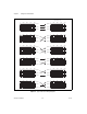
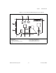
For example, if the diagram supplied with the motor matches the third
Type 2 diagram, wire Hall effect sensor 1 to input 3 on the UMI or
NI 7350, and then wire sensor 2 to input 1 and wire sensor 3 to input 2.
The Hall effect sensor inputs for Axes 1, 2, 5, and 6 are defined as
follows:
• Axis 1 uses digital port 4, bits 2–4, with bit 2 as input 1.
• Axis 2 uses digital port 4, bits 5–7, with bit 5 as input 1.
• Axis 5 uses digital port 8, bits 2–4, with bit 2 as input 1.
• Axis 6 uses digital port 8, bits 5–7, with bit 5 as input 1.
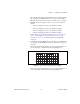
Refer to Figure 5-7, 68-Pin Digital I/O Connector Pin Assignments
(Ports 1–4), and Figure 5-8, 68-Pin Digital I/O Connector Pin
Assignments (Ports 5–8), for detailed pinouts of the digital I/O
connectors.
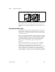
3. Configure the system in MAX. There are two base types of Hall effect
sensor inputs. Set the NI-Motion software to the base sensor type you
are using.
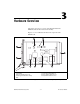
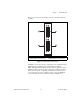
If the motor documentation matches any of the patterns in Figure 2-1,
you are using Type 1, which matches the graph in Figure 2-3.
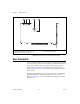
Figure 2-3. Type 1 Hall Sensor Phasing Sequence Diagram
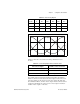
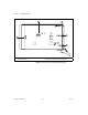
If the motor documentation matches any of the patterns in Figure 2-2,
you are using Type 2, which matches the graph in Figure 2-4.
0° 180° 360° 540° 720°
1
2
3