PXI NI PXI-4224 User Manual NI PXI-4224 User Manual August 2008 373752G-01
Support Worldwide Technical Support and Product Information ni.
Important Information Warranty The NI PXI-4224 is warranted against defects in materials and workmanship for a period of one year from the date of shipment, as evidenced by receipts or other documentation. National Instruments will, at its option, repair or replace equipment that proves to be defective during the warranty period. This warranty includes parts and labor.
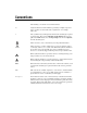
Conventions The following conventions are used in this manual: <> Angle brackets that contain numbers separated by an ellipsis represent a range of values associated with a bit or signal name—for example, AO <3..0>. » The » symbol leads you through nested menu items and dialog box options to a final action. The sequence File»Page Setup»Options directs you to pull down the File menu, select the Page Setup item, and select Options from the last dialog box.
Contents Chapter 1 About the NI PXI-4224 What You Need to Get Started ......................................................................................1-2 National Instruments Documentation ............................................................................1-3 Installing the Application Software, NI-DAQ, and the DAQ Device ...........................1-3 Installing the NI PXI-4224 ............................................................................................
Contents Chapter 5 Using the NI PXI-4224 Developing Your Application ....................................................................................... 5-1 Typical Program Flow Chart........................................................................... 5-1 Overview of Typical Flow Chart .................................................................... 5-3 Creating a Task Using DAQ Assistant or Programmatically ........... 5-3 Adjusting Timing and Triggering.....................................
Contents Figures Figure 2-1. Figure 2-2. Figure 2-3. Figure 2-4. Figure 2-5. Figure 2-6. Figure 2-7. Figure 2-8. Figure 2-9. NI PXI-4224 Front Label ......................................................................2-3 Unshielded Floating Signal Source Connection Using a D-SUB Connector ....................................................................2-4 Unshielded Grounded Signal Source Connection Using a D-SUB Connector ....................................................................
Contents Tables Table 2-1. NI PXI-4224 25-Pin D-SUB Terminal Pin Assignments ..................... 2-2 Table 4-1. Table 4-2. Signal Conditioning Functional Blocks ................................................ 4-3 PXI Trigger Bus Timing Signals .......................................................... 4-9 Table 5-1. Table 5-2. Table 5-3. NI-DAQmx Properties .......................................................................... 5-4 Programming a Task in LabVIEW ..................................
1 About the NI PXI-4224 This chapter provides an introduction to the NI PXI-4224 device and its installation. The NI PXI-4224 is part of the NI PXI-4200 series of data acquisition (DAQ) devices with integrated signal conditioning. The PXI-4200 series reduces measurement setup and configuration complexity by integrating signal conditioning and DAQ on the same product. The NI PXI-4224 is an 8-channel isolated analog input device with a ±10 V input range.
Chapter 1 About the NI PXI-4224 What You Need to Get Started To set up and use the NI PXI-4224, you need the following: ❑ Hardware – NI PXI-4224 – One of the following: – • TB-2725 terminal block • 25-pin D-SUB female connector PXI or PXI/SCXI combination chassis ❑ Software – NI-DAQ 7.3.
Chapter 1 About the NI PXI-4224 National Instruments Documentation The NI PXI-4224 User Manual is one piece of the documentation set for your DAQ system. You could have any of several types of manuals depending on the hardware and software in your system. Use the manuals you have as follows: • DAQ Getting Started Guide—This document describes how to install NI-DAQ devices and NI-DAQ. Install NI-DAQmx before you install the SCXI module.
Chapter 1 About the NI PXI-4224 Installing the NI PXI-4224 Refer to the Read Me First: Radio-Frequency Interference document before removing equipment covers or connecting or disconnecting any signal wires. Note Refer to the DAQ Getting Started Guide to unpack, install, and configure the NI PXI-4224 in a PXI chassis, and then to the SCXI Quick Start Guide if you are using a PXI/SCXI combination chassis.
2 Connecting Signals This chapter provides details about the front signal connector of the NI PXI-4224 and how to connect signals to the NI PXI-4224. Connecting Signals to the NI PXI-4224 After you have verified that the NI PXI-4224 is installed correctly and self-tested the device, refer to the following sections to connect signals to the device.
Chapter 2 Connecting Signals The PFI 0/CAL SMB connector is for low-voltage timing and calibration signals only. Voltages greater than ±15 V can damage the device. Caution If you are building a 25-pin D-SUB connector for your application, make sure you use a connector and wires that are safety rated for the voltage and category of the signals in your application. Table 2-1.
Chapter 2 NI PXI-4224 8 Chan Isolation Amp ACCESS Connecting Signals 1 ACTIVE PFI 0/ CAL 2 1 3 4 5 6 7 8 9 10 11 12 13 ACCESS and ACTIVE LEDs SMB PFI 0/CAL Connector 2 14 15 16 17 18 19 20 21 22 23 24 25 1 2 3 3 25-Pin D-SUB or TB-2725 Terminal Block Connector Figure 2-1.
Chapter 2 Connecting Signals In the electrical diagrams, two different ground symbols are used. These symbols indicate that you cannot assume that the indicated grounds are at the same potential. Refer to Appendix A, Specifications, for maximum working voltage specifications. You can make signal connections to the NI PXI-4224 through either an NI terminal block, such as the TB-2725, or you can build a connector using a 25-pin D-SUB.
Chapter 2 Signal Source VSIG Twisted-Pair Wiring Connecting Signals CH 0 AI 0 + + – AI 0 – VSIG Ground Reference CH 7 AI 7 + AI 7 – Figure 2-3.
Chapter 2 Connecting Signals Signal Source Twisted-Pair Wiring Shielding CH 0 AI 0 + VSIG + – AI 0 – CH 7 AI 7 + AI 7 – Figure 2-4. Shielded Floating Signal Source Connection Using a D-SUB Connector NI PXI-4224 User Manual 2-6 ni.
Chapter 2 Twisted-Pair Wiring Shielding Signal Source Connecting Signals CH 0 AI 0 + VSIG + – AI 0 – VSIG Ground Reference CH 7 AI 7 + AI 7 – Figure 2-5.
Chapter 2 Connecting Signals Figures 2-6 through 2-9 illustrate connecting signals using a terminal block. Signal Source VSIG Terminal Block Twisted-Pair Wiring CH 0 AI 0 + + – AI 0 – CH 7 AI 7 + AI 7 – Figure 2-6. Unshielded Floating Signal Source Connection Using a Terminal Block NI PXI-4224 User Manual 2-8 ni.
Chapter 2 Terminal Block Signal Source VSIG Connecting Signals CH 0 Twisted-Pair Wiring AI 0 + + – AI 0 – VSIG Ground Reference CH 7 AI 7 + AI 7 – Figure 2-7.
Chapter 2 Connecting Signals Signal Source Twisted-Pair Wiring Shielding Terminal Block CH 0 AI 0 + VSIG + – AI 0 – CH 7 AI 7 + AI 7 – Figure 2-8. Shielded Floating Signal Source Connection Using a Terminal Block NI PXI-4224 User Manual 2-10 ni.
Chapter 2 Signal Source Twisted-Pair Wiring Shielding Terminal Block Connecting Signals CH 0 AI 0 + VSIG + – AI 0 – VSIG Ground Reference CH 7 AI 7 + AI 7 – Figure 2-9. Shielded Grounded Signal Source Connection Using a Terminal Block Floating Signal Source Connection Figures 2-2, 2-4, 2-6, and 2-8 illustrate floating signal source connections. In this configuration, the signal source being measured is a floating signal source, such as a battery.
Chapter 2 Connecting Signals Ground-Referenced Signal Connection Figures 2-3, 2-5, 2-7, and 2-9 illustrate the ground-referenced signal connection. In this configuration, the voltage source being measured is referenced to its own ground reference that is connected through a conductive path to the instrument ground reference. For example, the path can be through a common earth ground or through the power line ground.
3 Configuring and Testing This chapter provides details about configuring and testing the NI PXI-4224 in MAX, including how to use device test panels and create and configure NI-DAQmx Tasks and NI-DAQmx Global Channels. Verifying and Self-Testing the Signals Using Test Panels After you have successfully installed the NI PXI-4224, verified the installation, and connected the signals, use the NI PXI-4224 device test panels to verify the device is measuring signals properly.
Chapter 3 Configuring and Testing Configuring the NI PXI-4224 in MAX This section describes how to create NI-DAQmx Tasks and NI-DAQmx Global Channels in MAX that allow you to take measurements with the NI PXI-4224. Creating a Voltage Task or Global Channel Using NI-DAQmx An NI-DAQmx Global Channel gives a physical channel a name and provides scaling. An NI-DAQmx Task is a collection of channels with timing and triggering configured.
Chapter 3 Configuring and Testing Verifying and Self-Testing an NI-DAQmx Task or Global Channel After you have created an analog input voltage NI-DAQmx Task or NI-DAQmx Global Channel, verify the NI-DAQmx Task or NI-DAQmx Global Channel signal and functionality using the Test button in the toolbar: 1. If you created an NI-DAQmx Task, set the timing and triggering settings you wish to use in the test in the Task Timing and Task Triggering tabs. 2.
4 Theory of Operation This chapter describes the theory of operation, measurement considerations, and timing information. Theory of Operation Figure 4-1 illustrates the key functional components of the NI PXI-4224, including the DAQ and integrated signal conditioning circuitry.
NI PXI-4224 User Manual 4-2 PGA PGA PGA Input Protection Input Protection Input Protection AI6 AI7 AI3 AI5 PGA Input Protection AI2 PGA PGA Input Protection AI1 Input Protection PGA Input Protection AI0 AI4 PGA Input Protection Opto Isolation ISO Amp Opto Isolation ISO Amp Opto Isolation ISO Amp Opto Isolation ISO Amp Opto Isolation ISO Amp Opto Isolation ISO Amp Opto Isolation ISO Amp Opto Isolation ISO Amp Post Filter Post Filter Post Filter Post Filter Post Fi
Chapter 4 Theory of Operation Signal Conditioning Functional Overview The NI PXI-4224 is part of the PXI-4200 series of DAQ devices with integrated signal conditioning designed to provide application-specific signal conditioning, DAQ, and integrated field wiring connectivity on the same product. The NI PXI-4224 signal conditioning circuitry is designed to provide attenuation, amplification, and filtering capabilities as described in Table 4-1. Table 4-1.
Chapter 4 Theory of Operation Signal Source Source Impedance RS VSIG + – + CIN 100 pF RIN Input Impedance – Measured Voltage VMEAS Figure 4-2. Effect of Input Impedance on Signal Measurements Although RS does not influence DC measurements, take care when measuring AC signals since CIN attenuates higher frequencies if RS is too large.
Chapter 4 Theory of Operation Effective CMR When the frequency of a common-mode signal is known and outside of the measurement frequency band of interest, you can use an analog or digital filter, or both, to further reduce the residual error left from the finite CMRR of the instrument. The combined CMR of the instrument and the filter attenuation results in an effective CMR.
Chapter 4 Theory of Operation PXI Trigger<0..5> AI CONV CLK PXI Star PFI 0 Ctr 0 Internal Output Figure 4-3. AI CONV CLK Signal Routing Figure 4-3 shows that AI CONV CLK can be generated from a number of sources, such as the external signals PFI 0, PXI_Trig<0..5>, and PXI_Star, and the Ctr 0 Internal Output. Programmable Function Inputs PFI 0 is connected to the front SMB connector of the NI PXI-4224. Software can select PFI 0 as the external source for a given timing signal.
Chapter 4 Theory of Operation Device and PXI Clocks Many functions performed by the NI PXI-4224 require a frequency timebase to generate the necessary timing signals for controlling A/D conversions, digital-to-analog converter (DAC) updates, or general-purpose signals at the I/O connector. The NI PXI-4224 can use either its internal 20 MHz master timebase or a timebase received over the PXI trigger bus on the PXI clock line. These timebases are software configurable.
Chapter 4 Theory of Operation Figure 4-4 shows this signal connection scheme. DAQ-STC AI REF TRIG RTSI Switch PXI Bus Connector AI START TRIG PXI Trigger<0..5> PXI Star AI CONV CLK AI SAMP CLK AI PAUSE TRIG AI SAMPLE CLK TIMEBASE PXI Trigger<7> Switch Master Timebase Figure 4-4. NI PXI-4224 PXI Trigger Bus Signal Connection NI PXI-4224 User Manual 4-8 ni.
Chapter 4 Theory of Operation Table 4-2 provides more information about each of the timing signals available on the PXI trigger bus. For more detailed timing signal information, refer to Appendix B, Timing Signal Information. Table 4-2. PXI Trigger Bus Timing Signals Signal AI START TRIG Direction Description Availability Availability on PFI 0 on PXI SMB Trigger Bus Input This trigger is the source for the analog input digital start trigger, which is the trigger that begins an acquisition.
5 Using the NI PXI-4224 This chapter describes how to program the NI PXI-4224, using DAQ Assistant or LabVIEW, and how to calibrate the device. Developing Your Application This section describes the software and programming steps necessary to use the NI PXI-4224. For more information about a particular software or programming process, refer to your ADE documentation.
Chapter 5 Using the NI PXI-4224 Yes Create Task Using DAQ Assistant? No Create Task in DAQ Assistant or MAX Create a Task Programmatically Create AI Voltage Channel Further Configure Channels? No No Yes Configure Channels Hardware Timing/Triggering? Yes Adjust Timing Settings Start Measurement Yes Analyze Data? Read Measurement Process Data Yes Graphical Display Tools Yes No Display Data? No Continue Sampling? No Stop Measurement Clear Task Figure 5-1.
Chapter 5 Using the NI PXI-4224 Overview of Typical Flow Chart The following sections briefly discuss some considerations for some of the steps in Figure 5-1. These sections are meant to provide an overview of some of the options and features available when programming with NI-DAQmx. Creating a Task Using DAQ Assistant or Programmatically When creating an application, you must first decide whether to create the task using the DAQ Assistant or programmatically in the ADE.
Chapter 5 Using the NI PXI-4224 When programmatically adjusting timing settings, you can set the task to acquire continuously, acquire a buffer of samples, or acquire one point at a time. For continuous and buffered acquisitions, you can set the acquisition rate and the number of samples to read. By default, the clock settings are automatically set by an internal clock based on the requested sample rate.
Chapter 5 Using the NI PXI-4224 Acquiring, Analyzing, and Presenting After configuring the task and channels, you can start your acquisition, read measurements, analyze the data returned, and display it according to the needs of your application. Typical methods of analysis include digital filtering, averaging data, performing harmonic analysis, applying a custom scale, or adjusting measurements mathematically.
Chapter 5 Using the NI PXI-4224 Table 5-2. Programming a Task in LabVIEW Flowchart Step VI or Program Step Create Task in DAQ Assistant Create a DAQmx Task Name Constant located on the Controls»All Controls»I/O»DAQmx Name Controls subpalette, right-click it, and select New Task (DAQ Assistant). Create a Task Programmatically (optional) DAQmx Create Task.
Chapter 5 Using the NI PXI-4224 Table 5-2. Programming a Task in LabVIEW (Continued) Flowchart Step VI or Program Step Continue Sampling For continuous sampling, use a While Loop. If you are using hardware timing, you also need to set the DAQmx Timing.vi sample mode to Continuous Samples. To set the VI, right-click the terminal of the DAQmx Timing.vi labeled sample mode and click Create»Constant. Click the box and select Continuous Samples. Stop Measurement DAQmx Stop Task.vi—This VI is optional.
Chapter 5 Using the NI PXI-4224 8. Once you have added the property to the property node, right-click the terminal to change the attributes of the property, or to add a control, constant, or indicator. 9. To add another property to the property node, right-click an existing property and left-click Add Element. To change the new property, left-click it and select the property you wish to define. You can also drag the bottom of the property node down to add more channels to the node.
Chapter 5 Using the NI PXI-4224 Create a Master Task (optional) Configure Slave Timing Create Master AI Voltage Channels Set Slave to Use Timebase from Master Configure Master Channel Configure Slave Triggering Configure Master Timing Get Master Timebase Source and Rate from Master Task Start Slave Measurement(s) Create a Slave Task (optional) Start Master Measurement Create Slave AI Voltage Channels Read Measurement Configure Slave Channel Continue Sampling? Yes No More Slave Tasks? Yes
Chapter 5 Using the NI PXI-4224 Synchronizing the NI PXI-4224 Using LabVIEW This section describes in more detail the steps shown in Figure 5-2, such as how to create a task in LabVIEW and configure the channels of the NI PXI-4224. For further instructions, select Help»VI, Function, & How-To Help from the LabVIEW menu bar.
Chapter 5 Using the NI PXI-4224 Table 5-3. Synchronizing the NI PXI-4224 Using LabVIEW (Continued) Flowchart Step VI or Program Step Set Slave to Use Timebase from Master Use a DAQmx Timing Property Node to set MasterTimebase.Src and MasterTimebase.Rate to the values retrieved from the master task in the Get Master Timebase Source and Rate from Master Task step. Configure Slave Triggering DAQmx Trigger.
Chapter 5 Using the NI PXI-4224 Calibrating the NI PXI-4224 Calibration refers to the process of minimizing measurement errors. On the NI PXI-4224, errors from the digitizer components of the DAQ device circuitry are corrected in the analog circuitry by onboard calibration digital-to-analog converters (CalDACs). Errors from the signal conditioning circuitry are corrected in software. Three levels of calibration are available for the NI PXI-4224 to ensure the accuracy of its analog circuitry.
Chapter 5 Using the NI PXI-4224 4. Right-click the NI PXI-4224 and select Self-Calibrate. 5. A dialog box opens indicating that the NI PXI-4224 is self-calibrating. 6. When the dialog box closes, the NI PXI-4224 is successfully self-calibrated. Note The NI PXI-4224 also can be self-calibrated programmatically by using DAQmx Self Calibrate.vi in LabVIEW.
A Specifications This appendix lists the specifications for the NI PXI-4224 device. These specifications are typical at 25 °C unless otherwise noted. Overvoltage Protection Powered on or off................................... 42.4 Vpeak or 60 VDC max PFI 0/CAL SMB connector.................... ±15 V, powered on or off Analog Input Number of input channels ...................... 8 Input range ............................................. ±10 VDC Resolution ..............................................
Appendix A Specifications for Input coupling.........................................DC Bandwidth, –3 dB ...................................15 kHz Slew rate .................................................2 V/μs typical Input impedance Powered on ......................................100 MΩ parallel 100 pF Powered off .....................................30 kΩ Input bias current ....................................100 pA CMRR Balanced ..........................................
Appendix A Specifications for Calibration Recommended warm-up time ................ 30 minutes External calibration interval................... 1 year Pre-Calibration Errors1 Pre-calibration offset error relative to input (RTI) ............................ 865 mV max Signal conditioning component only............................... ±50 mV typ, ±160 mV max at a gain of 1 Pre-calibration gain error ....................... ±18,900 ppm max Signal conditioning component only...............................
Appendix A Specifications for Response .................................................Rising or falling edge, software programmable Pulse width .............................................10 ns min Impedance...............................................10 kΩ Coupling .................................................DC PXI Trigger Bus Trigger lines............................................6 Star trigger ..............................................
Appendix A Specifications for Weight .................................................... 279 g (9.8 oz) Analog input signal connector ............... 25-Pin D-SUB Maximum Working Voltage (Signal + common-mode) each input should remain within 42.4 Vpeak or 60 VDC of ground. Maximum working voltage refers to the signal voltage plus the CMV. Channel-to-earth (inputs) ....................... 42.4 Vpeak or 60 VDC, Measurement Category I Channel-to-channel (inputs)................... 42.
Appendix A Specifications for Safety This product meets the requirements of the following standards of safety for electrical equipment for measurement, control, and laboratory use: • IEC 61010-1, EN 61010-1 • UL 61010-1, CSA 61010-1 Note For UL and other safety certifications, refer to the product label or the Online Product Certification section.
Appendix A Specifications for Environmental Management NI is committed to designing and manufacturing products in an environmentally responsible manner. NI recognizes that eliminating certain hazardous substances from our products is beneficial to the environment and to NI customers. For additional environmental information, refer to the NI and the Environment Web page at ni.com/environment.
Timing Signal Information B This appendix contains additional information about the timing signals discussed in Chapter 4, Theory of Operation. Connecting Timing Signals Caution Exceeding the maximum input voltage ratings listed in Appendix A, Specifications, can damage the device and the computer. NI is not liable for any damage resulting from such signal connections.
Appendix B Timing Signal Information DAQ Timing Connections The timing signals are AI START TRIG, AI REF TRIG, AI SAMP CLK, AI CONV CLK, AI PAUSE TRIG, AI SAMPLE CLK TIMEBASE, and AI HOLD COMPLETE. Posttriggered DAQ allows you to view data that is acquired after a trigger event is received. Figure B-1 shows a typical posttriggered sequence. AI START TRIG AI SAMP CLK AI CONV CLK Scan Counter 4 3 2 1 0 Figure B-1.
Appendix B Timing Signal Information AI START TRIG Signal The AI START TRIG signal can be input or output through PFI 0, PXI_Trig<0..5>, or PXI_Star. As an input, AI START TRIG is configured in the edge-detection mode. You can select PFI 0 as the source for AI START TRIG and configure the polarity selection for either rising or falling edge. The selected edge of AI START TRIG starts the sequence for both posttriggered and pretriggered acquisitions.
Appendix B Timing Signal Information The device also uses AI START TRIG to initiate pretriggered operations. In pretriggered applications, AI START TRIG is generated by a software trigger unless a PFI pin is selected as the source of AI START TRIG. Refer to the AI REF TRIG Signal section for a complete description of the use of AI START TRIG and AI REF TRIG in a pretriggered operation. AI REF TRIG Signal The AI REF TRIG signal can be input through PFI 0, PXI_Trig<0..5>, or PXI_Star.
Appendix B Timing Signal Information tw tw = 50 to 100 ns Figure B-6. AI REF TRIG Output Signal Timing AI SAMP CLK Signal The AI SAMP CLK signal can be externally input from PFI 0, PXI_Trig<0..5>, or PXI_Star. It can be output on any PXI trigger bus line. Refer to Figures B-1 and B-2 for the relationship of AI SAMP CLK to the sequence. As an input, AI SAMP CLK is configured in edge-detection mode. You can configure the polarity selection for either rising or falling edge.
Appendix B Timing Signal Information Figures B-7 and B-8 show the input and output timing requirements for AI SAMP CLK. tw Rising-Edge Polarity Falling-Edge Polarity tw = 10 ns minimum Figure B-7. AI SAMP CLK Input Signal Timing tw AI SAMP CLK tw = 50 to 100 ns a. Start of Scan Start Pulse AI CONV REF AI SAMP CLK toff = 10 ns minimum toff b. Scan in Progress, Two Conversions per Scan Figure B-8.
Appendix B Timing Signal Information AI SAMP CLK generates a conversion. Separate the AI SAMP CLK pulses by at least one scan period. A counter on the device internally generates AI SAMP CLK unless you select some external source. The AI START TRIG signal starts this counter, and the application software or the sample counter stops it. Scans generated by either an internal or external AI SAMP CLK are inhibited unless they occur within a sequence.
Appendix B Timing Signal Information tw tw = 50 to 100 ns Figure B-10. AI CONV CLK Output Signal Timing The ADC switches to hold mode within 60 ns of the selected edge. This hold-mode delay time is a function of temperature and does not vary from one conversion to the next. Separate the AI CONV CLK pulses by at least one conversion period. The NI PXI-4224 sample interval counter generates AI CONV CLK unless you select an external source.
Appendix B Timing Signal Information AI SAMPLE CLK TIMEBASE Signal PFI 0, PXI_Trig<0..5>, or PXI_Star can externally input the AI SAMPLE CLK TIMEBASE signal, which is not available as an output on the I/O connector. The onboard scan interval (SI) counter uses AI SAMPLE CLK TIMEBASE as a clock to time the generation of the AI SAMP CLK signal. Configure the pin you select as the source for AI SAMPLE CLK TIMEBASE in level-detection mode.
Appendix B Timing Signal Information AI HOLD COMPLETE Signal AI HOLD COMPLETE is an output-only signal that generates a pulse with the leading edge occurring approximately 50 to 100 ns after an A/D conversion begins. The polarity of this output is software configurable, but the polarity is typically configured so that a low-to-high leading edge can clock external analog input multiplexers that indicate when the input signal has been sampled and can be removed.
Removing the NI PXI-4224 C This appendix provides details for removing an NI PXI-4224 device from MAX and from a PXI or PXI/SCXI combination chassis. You must physically remove the NI PXI-4224 from the chassis before you can remove it from MAX. Note Removing the NI PXI-4224 from a PXI or PXI/SCXI Combination Chassis Consult the PXI or PXI/SCXI chassis documentation for additional instructions and cautions.
Appendix C Removing the NI PXI-4224 Figure C-1. Injector/Ejector Handle Position Before Device Removal Removing the NI PXI-4224 from MAX To remove an NI PXI-4224 device from MAX, complete the following steps after launching MAX: 1. Expand Devices and Interfaces to display the list of installed devices and interfaces. The NI PXI-4224 should have a red circle with a white X inside it next to the device to indicate it has been physically removed from the chassis. 2.
D Common Questions This appendix lists common questions related to the use of the NI PXI-4224. Which version of NI-DAQ works with the NI PXI-4224 and how do I get the most current version of NI-DAQ? You must have NI-DAQ 7.3.1 or later and use NI-DAQmx. 1. Go to ni.com. 2. Follow the link, Download Software»Drivers and Updates» Search Drivers and Updates. 3. Enter the keyword NI-DAQ to find the latest version of NI-DAQ for your operating system.
Appendix D Common Questions How do I perform an external calibration of the NI PXI-4224? As of the NI PXI-4224 release, an external calibration document is not available. To check the availability of an NI PXI-4224 external calibration document is go to ni.com/calibration and click Manual Calibration Procedures. NI PXI-4224 User Manual D-2 ni.
Glossary Symbol Prefix Value p pico 10 –12 n nano 10 –9 μ micro 10 – 6 m milli 10 –3 k kilo 10 3 M mega 10 6 G giga 10 9 T tera 10 12 Symbols / Per. ° Degree. % Percent. + Positive of, or plus. – Negative of, or minus. Ω Ohm. A A Amperes. A/D Analog-to-digital. AC Alternating current.
Glossary ADC Analog-to-digital converter—An electronic device, often an integrated circuit, that converts an analog voltage to a digital number. ADE Application development environment. AI Analog input. AI CONV CLK Convert signal. AI HOLD COMPLETE Scan clock signal. AI PAUSE TRIG Analog input gate signal. AI SAMP CLK Start scan signal. B bandwidth The range of frequencies present in a signal, or the range of frequencies to which a measuring device can respond.
Glossary CMR Common-mode rejection. CMRR Common-mode rejection ratio—A measure of an instrument’s ability to reject interference from a common-mode signal, usually expressed in decibels (dB). common-mode signal Any voltage present at the instrumentation amplifier inputs with respect to amplifier ground. counter/timer A circuit that counts external pulses or clock pulses (timing). D D/A Digital-to-analog. D GND Digital ground signal.
Glossary DMA Direct memory access—A method by which data can be transferred to/from computer memory from/to a device or memory on the bus while the processor does something else. DMA is the fastest method of transferring data to/from computer memory. DNL Differential nonlinearity—A measure in least significant bit of the worst-case deviation of code widths from their ideal value of 1 LSB. driver Software that controls a specific hardware device such as a DAQ device.
Glossary H h Hour or hours. Hz Hertz—The number of scans read or updates written per second. I I/O Input/output—The transfer of data to/from a computer system involving communications channels, operator interface devices, and/or DAQ and control interfaces. in. Inch or inches. INL Integral nonlinearity—A measure in LSB of the worst-case deviation from the ideal A/D or D/A transfer characteristic of the analog I/O circuitry. input bias current The current that flows into the inputs of a circuit.
Glossary L LabVIEW Laboratory Virtual Instrument Engineering Workbench—A program development application based on the programming language G and used commonly for test and measurement purposes. LED Light-emitting diode. linearity The adherence of device response to the equation R = KS, where R = response, S = stimulus, and K = a constant. LSB Least significant bit. M MAX Measurement & Automation Explorer—NI software for configuring devices and channels.
Glossary N NI-DAQmx The latest NI-DAQ driver with new VIs, functions, and development tools for controlling measurement devices. noise An undesirable electrical signal—Noise comes from external sources such as the AC power line, motors, generators, transformers, fluorescent lights, soldering irons, CRT displays, computers, electrical storms, welders, radio transmitters, and internal sources such as semiconductors, resistors, and capacitors. Noise corrupts signals you are trying to send or receive.
Glossary R relative accuracy A measure in LSB of the accuracy of an ADC. It includes all nonlinearity and quantization errors. It does not include offset and gain errors of the circuitry feeding the ADC. resolution The smallest signal increment that can be detected by a measurement system. Resolution can be expressed in bits, in proportions, or in percent of full scale. For example, a system has 16-bit resolution, one part in 65,536 resolution, and 0.0015% of full scale.
Glossary SCXI Signal Conditioning eXtensions for Instrumentation—The NI product line for conditioning low-level signals within an external chassis near sensors so only high-level signals are sent to DAQ devices in the noisy PC environment. self-calibrating A property of a DAQ device that has an extremely stable onboard reference and calibrates its own A/D and D/A circuits without manual adjustments by the user. signal conditioning The manipulation of signals to prepare them for digitizing.
Glossary W waveform Multiple voltage readings taken at a specific sampling rate. working voltage The highest voltage with respect to ground that should be applied to an input terminal during normal use, normally well under the breakdown voltage for safety margin. Includes both the signal and common-mode voltages. NI PXI-4224 User Manual G-10 ni.
Index A analog input connections, 2-3 ground-referenced signal connection (recommended) (figure), 2-12 shielded, 2-12 specifications, A-1 application development acquiring data, 5-5 adjusting timing and triggering, 5-3 analyzing data, 5-5 clearing tasks and memory, 5-5 configuring channel properties, 5-4 creating tasks programmatically, 5-3 using DAQ Assistant, 5-3 documentation, 5-11 example programs (note), 5-1 presenting data, 5-5 synchronizing multiple devices overview, 5-8 program flow chart (figure),
Index AI REF TRIG signal input signal timing (figure), B-4 output signal timing (figure), B-5 overview, B-4 AI SAMP CLK signal input signal timing (figure), B-6 output signal timing (figure), B-6 overview, B-5 AI SAMPLE CLK TIMEBASE signal description (table), 4-9 overview, B-9 signal timing (figure), B-9 AI START TRIG signal description (table), 4-9 input signal timing (figure), B-3 output signal timing (figure), B-3 overview, B-3 posttriggered sequence (figure), B-2 pretriggered sequence (figure), B-2 ty
Index F M floating signal source connection connecting to NI PXI-4224, 2-11 front signal connector, 2-1 front label of NI PXI-4224 (figure), 2-3 signal assignments of NI PXI-4224 (table), 2-2 MAX.
Index Q signal conditioning overview, 4-3 timing and control overview, 4-5 NI-DAQ software, 1-3, D-1 NI-DAQmx channel properties, configuring (table), 5-4 NI-DAQmx Global Channel creating, 3-2 verifying and self-testing, 3-3 NI-DAQmx Task creating, 3-2 verifying and self-testing, 3-2 questions and answers, D-1 R regulatory compliance specifications, A-6 removing NI PXI-4224 from Measurement & Automation Explorer (MAX), C-2 from PXI chassis, C-1 S O safety specifications, A-6 self-calibration, 5-12 se
Index timing connections DAQ timing connections typical posttriggered acquisition (figure), B-2 typical pretriggered acquisition (figure), B-2 overview, B-1 programmable function input connections, B-1 timing signal routing device and PXI clocks, 4-7 programmable function inputs, 4-6, B-1 timing signals. See DAQ timing connections transfer characteristic specifications, A-2 trigger bus.