USER GUIDE MID-7654/7652 SERVO POWER MOTOR DRIVE This user guide describes the electrical and mechanical aspects of the MID-7654/7652 servo power motor drive and describes how to use the MID-7654/7652 with your motion controller. Contents Conventions ............................................................................................ 2 Introduction ............................................................................................. 2 What You Need to Get Started ..........................
Modifying the Power Entry Module........................................................30 Replacing a Fuse...............................................................................30 Changing the Line Voltage...............................................................31 Amplifier/Driver Command Signals .......................................................31 Specifications...........................................................................................31 Technical Support Resources .....
The MID-7654/7652 simplifies your field wiring through separate encoder, limit switch, and motor power removable screw terminal connector blocks for each axis. The terminal blocks do not require any special wiring tools for installation. The MID-7654/7652 connects to National Instruments motion controllers via a 68-pin, high-density interconnect cable. The MID-7654/7652 has four levels of amplifier inhibit/disable protection for motion system shut down.
qualified to do so and disconnect all field power prior to removing covers or shields. • Do not operate damaged equipment. The safety protection features built into this device can become impaired if the device becomes damaged in any way. If the device is damaged, turn the device off and do not use it until service-trained personnel can check its safety. If necessary, return the device to National Instruments for service and repair to ensure its safety is not compromised.
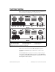
Front Panel Switches Figure 1 shows the front panel for your MID-7654/7652. The DIP switches are shown with the detachable metal cover plate removed.
The ENABLE switch enables or inhibits the servo amplifiers. If the ENABLE switch is in the inhibit position (OFF), the amplifier output stages are inhibited and the yellow LEDs for all axes illuminate. See the Front Panel LEDs section of this guide for more information. Both the AC POWER and ENABLE switches can inhibit the servo amplifiers. However, as long as the AC POWER switch is on, only the servo amplifier output stages are disabled.
Table 1. Front Panel LED Indicators Status Motor Axis Amplifier Fault Output (red) 1 2 3* 4* Amplifier Inhibit (yellow) 1 2 3* 4* Limit Status (green) 1 2 3* 4* * These LEDs only appear on the MID-7654. Amplifier Fault Output LEDs The top row of the LED status array indicates the status of the amplifiers. A red LED indicates an overcurrent condition, a short circuit condition, an over temperature condition, or a problem with the motor bus voltage on that axis.
Front Panel DIP Switch Settings The MID-7654/7652 front panel has a detachable metal plate that, when removed, provides access to one 4-position DIP switch bank and either four (MID-7654) or two (MID-7652) 9-position DIP switch banks. Refer to Figure 1 for the location of these switches. Use the DIP switches on the 4-position DIP switch bank to configure the inhibit in, inhibit out, and limit status LED polarity as shown in Figure 2.
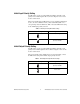
Inhibit Input Polarity Setting Use DIP switch 1 on the 4-position DIP switch bank to globally set the polarity for the inhibit input for all axes. Refer to Figures 1 and 3 for the location of this switch. The factory-default setting of DIP switch 1 is active-low. If the inhibit input is active, the axis is inhibited and the yellow status LED (middle row) corresponding to that axis illuminates. Table 2 shows the DIP switch setting for the inhibit input polarity selection. Table 2.
Limit Status LED Polarity Setting Use DIP switch 3 on the 4-position DIP switch bank to globally set the polarity for the Limit Status LED. Refer to Figures 1 and 3 for the location of this switch. The factory-default setting is active-high. Typically, you set the switch to match your controller’s polarity setting, so if either the reverse or forward limits for an axis are active, the green status LED (on the bottom row) corresponding to that axis illuminates.
Figure 4 illustrates the command voltage input to current output relationship for periods of time less than 2.7 seconds. +Vmax +I cont 0A 0V Output Current Input Command Voltage +I peak –I cont –V max Gain Applied –I peak Figure 4. Input Voltage to Output Current Relationship for Periods of Time Less Than 2.7 Seconds Figure 5 shows the command voltage input to current output relationship for periods of time greater than 2.7 seconds.
The amplifier peak and continuous current limits have been factory set for 5 A continuous current output and 10 A peak current output. Verify that these settings are appropriate for your application before powering your motors. Use DIP switches 1 through 4 on each of the 9-position DIP switch banks to set the continuous current limit for each axis. Use DIP switches 5 through 8 on each of the 9-position DIP switch banks to set the peak current limit for each axis.
If you are connecting multiple motors to your MID-7654/7652, verify that the total power dissipated by the motors at any given time is less than the total power the drive can provide. If the total power requirement exceeds the capability of the drive at any point, the drive will provide less power to the motors than desired until the total power requirement drops back down. Your MID-7654/7652 may overheat under continuous operation with loads that exceed specified limits.
Use the last DIP switch on each of the 9-position DIP switch banks to set the motor inductance level for each axis. Refer to Figures 1 and 3 for the location of the of the motor inductance level switch. Table 7 shows the DIP switch settings for low and standard motor inductance. Table 7. Motor Inductance Level DIP Switch Settings Switch Setting Operation Low motor inductance O N 9 Standard motor inductance (factory default) O N 9 MID-7654/7652 Servo Power Motor Drive User Guide 14 ni.
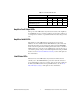
Back Panel Connector Wiring Figure 6 shows the MID-7654/7652 back panel connectors without their rear guards.
Be sure to turn off the ENABLE and AC POWER switches for your MID-7654/7652 and host computer and disconnect the unit from the power outlet before making connections to your motion controller. Caution The servo motor connectors on this drive are energized when the unit is powered on. The rear guard must be in place at all times while the unit is connected to a power outlet.
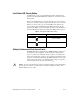
Terminal Block Wiring This section describes how to wire the terminal blocks on your MID-7654/7652. Servo Motor Power Terminal Blocks For motor power wiring, each MID-7654/7652 axis has a separate 5-position removable screw terminal block. Figure 7 shows a typical servo motor configuration pin assignment. The dotted loop indicates a shielded cable. + Motor + Motor – Motor Case Ground – Shield Servo Motor 1 2 3 4 5 Figure 7.
Depending on your motor, you may need to reverse the connections shown in Figure 7, as there is no industry standard for direction of movement relative to the positive and negative motor inputs. Table 8 shows the National Instruments motion control standard directional polarity. Table 8.
Rear Guard The rear guard consists of the protection cover, protection plates, and bottom mounting plate as shown in Figure 9. 1 2 Bottom Mounting Plate Protection Cover 3 Protection Plate Figure 9.
L S A T N EN IT O UM A R N ST IN The rear guard installed on the MID-7654/7652 is shown in Figure 10. Figure 10. Rear Guard Installed on the MID-7654/7652 The servo motor connectors on this drive are energized when the unit is powered on. The rear guard must be in place at all times while the unit is connected to a power outlet. Disconnect the MID-7654/7652 unit from power outlet before connecting wires to or disconnecting wires from the servo motor connectors.
1 Protection Cover 2 Protection Plate Figure 11. Protection Cover and Protection Plates: Used Axes 1 & 2, Unused Axes 3 & 4. The protection plates for any unused axes should remain installed in the closed position at all times, as shown on axes 3 and 4 in Figure 11. For axes you are using, the protection plates must be removed, rotated, and re-installed in the open position, as shown on axes 1 and 2 in Figure 11.
7. Ensure that the rear guard is held securely in place before reconnecting your MID-7654/7652 to a power outlet. Encoder Terminal Blocks For quadrature incremental encoder signals, each MID-7654/7652 axis has a separate 8-position removable screw terminal block. Where applicable, the MID-7654/7652 accepts two types of encoder signal inputs: single-ended (TTL) or differential line driver. You can accommodate open-collector output encoders by using 2.2 kΩ pullup resistors to +5 VDC.
If you require other encoder power voltages, reference an external power supply to the Digital Ground signal on the 8-pin encoder terminal block. Note The MID-7654/7652 supports differential inputs for Phase A, Phase B, and Index signals. You can easily accommodate encoders with various phase relationships by swapping the signals and/or connecting them to the inverting inputs as required by your application. The Index signal must occur when both Phase A and Phase B signals are low, as shown in Figure 14.
Drain Shield Encoder A Encoder A Encoder B Encoder B Encoder Index Encoder Index +5 V Digital Ground Figure 15. Shielded Twisted Pairs Using an unshielded cable may produce noise, which can corrupt the encoder signals and cause lost counts, reduced accuracy, or other erroneous encoder and controller operation.
Breakpoint and Trigger Terminal Blocks Both the breakpoint and trigger connectors use a 6-pin removable terminal block. The trigger terminal block provides access to the trigger input lines, shutdown input line, and digital ground. The breakpoint terminal block provides access to the breakpoint output lines, the +5 V supplied by the MID-7654/7652, and the digital ground. Figures 17 and 18 show the breakpoint and trigger 6-position terminal block assignments.
Analog Input 1 Analog Input 2 Analog Input 3 Analog Input 4 Analog Reference (Output) Analog Input Ground 1 2 3 4 5 6 Figure 19. Analog Input Terminal Block Pin Assignment Analog Output 1 Analog Output 2 Analog Output 3 Analog Output 4 Analog Output Ground 1 2 3 4 5 Figure 20.
Cable Installation for CE Compliance Take the following additional steps to ensure CE Compliance: 1. Enclose the terminal block wires in a 360-degree shielded cable. This requires a braided shield. 2. Install the strain-relief bar on the MID-7654/7652 as described in the Accessories Included for Optional Use section of this guide. 3. Place all cables connecting to the back panel through the strain-relief bar, as follows: 4. a.
5. b. Lay the cables so that the braided shield makes full contact with the foam of the strain-relief bar. The braided shield must only make contact with the strain-relief bar, and no other part of the device. c. Lower the clamp and tighten the thumb nuts to remove all gaps between the foam and the cable shields. The foam should press around the shield of the cable to provide 360-degree grounding to the cable shield.
2 1 1 Rear Guard Assembly 2 Strain Relief Bar Figure 23. MID-7654/7652 with the Strain-Relief Bar Installed Panel Mount Kit Installation The panel mount kit allows you to mount the MID-7654/7652 inside a cabinet or enclosure. Attach the panel mount kit to the rear and front set of screw holes on the side panels of the MID-7654/7652, as shown in Figure 24, using the provided screws.
L S A T N EN IT O UM A R N ST IN 1 1 2 Rear Guard Assembly 2 Panel Mount Figure 24. MID-7654/7652 with the Panel Mount Kit Installed The strain-relief bar and panel mount kit cannot be installed at the same time, because they will not simultaneously fit under the sides of the bottom mounting plate. Note Modifying the Power Entry Module This section covers replacing fuses and switching the line voltage for your drive. Replacing a Fuse Follow these steps to replace a fuse on your MID-7654/7652: 1.
4. Push the fuse holder back into the power entry module with the same orientation you observed in step 2. 5. Close the hinged cover. Changing the Line Voltage Follow these steps to change the line voltage on your MID-7654/7652: 1. Pry open the hinged cover on the power entry module (number 7 in Figure 6). 2. Remove the fuse holder. 3. Replace the two fuses with the appropriate fuses for the desired line voltage as listed in the Specifications section. 4.
Continuous current limit .........................0.85–5 A (default 0.85 A) DC-bus motor voltage ............................48 VDC PWM frequency......................................32 kHz Continuous power output rating (all axes combined).................................400 W at 25% duty cycle Encoders Inputs ......................................................Quadrature, incremental Differential input threshold ....................± 0.3 V (typical) Single ended input threshold ..................
Analog Inputs Noise filter (RC time constant) .............. 10 µs Compatibility ......................................... Signal pass-through Analog Outputs Compatibility ......................................... Signal pass-through Step/Direction Outputs Compatibility ......................................... Signal pass-through Shutdown Input Compatibility ......................................... Signal pass-through User 5 V Supply Voltage range @ 0.5 A........................... 4.7–5.
AC power................................................Detachable AC power cord (IEC standard type) Motion I/O ..............................................68-pin female high density VHDCI type Environment Operating temperature ............................0 to 50 °C (32 to 122 °F) Storage temperature ................................–20 to 70 °C (–4 to 158 °F) Humidity .................................................10% – 90% (noncondensing) Maximum Altitude .................................
Safety Meets the requirements of the following standards for safety for electrical equipment for measurement, control, and laboratory use: • EN 61010-1:1993/A2:1995, IEC 61010-1:1990/A2:1995 • UL 3101-1:1993, UL 3111-1:1994, UL 3121-1:1998 • CAN/CSA C22.2 No. 1010.1:1992/A2:1997 UL Recognized to UL 508C, power conversion equipment, File # E208822 Electromagnetic Compatibility EMC/EMI............................................... CE, C-Tick and FCC Part 15 (Class A) Compliant. Electrical emissions...
Technical Support Resources NI Web Support National Instruments Web support is your first stop for help in solving installation, configuration, and application problems and questions. Online problem-solving and diagnostic resources include frequently asked questions, knowledge bases, product-specific troubleshooting wizards, manuals, drivers, software updates, and more. Web support is available through the Technical Support section of ni.com.