OPERATING INSTRUCTIONS AND SPECIFICATIONS NI 9201/9221 8-Channel, 12-Bit Analog Input Modules Français Deutsch ni.
This document describes how to use the National Instruments 9201 and National Instruments 9221 and includes specifications and terminal assignments for the NI 9201/9221. In this document, the NI 9201/9221 with screw terminal and NI 9201/9221 with DSUB are referred to inclusively as the NI 9201/9221. Visit ni.com/info and enter rdsoftwareversion to determine which software you need for the modules you are using.
Safety Guidelines Operate the NI 9201/9221 only as described in these operating instructions. This icon denotes that the component may be hot. Touching this component may result in bodily injury. Hot Surface Safety Guidelines for Hazardous Voltages You can connect hazardous voltages only to the NI 9201/9221 with screw terminal. Do not connect hazardous voltages to the NI 9201/9221 with DSUB. If hazardous voltages are connected to the module, take the following precautions.
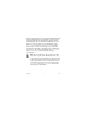
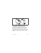
Make sure that devices and circuits connected to the module are properly insulated from human contact. Caution When module terminals are hazardous voltage LIVE (>42.4 Vpk/60 VDC), you must ensure that devices and circuits connected to the module are properly insulated from human contact. You must use the NI 9932 connector backshell kit to ensure that the terminals are not accessible. Caution Figure 1 shows the NI 9932 connector backshell.
Figure 1. NI 9932 Connector Backshell Safety Guidelines for Hazardous Locations The NI 9201/9221 is suitable for use in Class I, Division 2, Groups A, B, C, D, T4 hazardous locations; Class I, Zone 2, AEx nC IIC T4, and Ex nC IIC T4 hazardous locations; and nonhazardous locations only. Follow these guidelines if you are installing the NI 9201/9221 in a potentially explosive environment. Not following these guidelines may result in serious injury or death. © National Instruments Corp.
Caution Do not disconnect I/O-side wires or connectors unless power has been switched off or the area is known to be nonhazardous. Do not remove modules unless power has been switched off or the area is known to be nonhazardous. Caution Substitution of components may impair suitability for Class I, Division 2. Caution For Zone 2 applications, install the system in an enclosure rated to at least IP 54 as defined by IEC 60529 and EN 60529.
locations. If you are using the NI 9201/9221 in Gas Group IIC hazardous locations or in ambient temperatures of –40 °C ≤ Ta ≤ 70 °C, you must use the device in an NI chassis that has been evaluated as EEx nC IIC T4, Ex nA IIC T4, or Ex nL IIC T4 equipment. Special Conditions for Marine Applications Some modules are Lloyd’s Register (LR) Type Approved for marine applications. To verify Lloyd’s Register certification, visit ni.
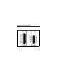
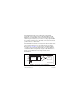
Connecting the NI 9201/9221 The NI 9201/9221 provides connections for eight analog input channels. AI0 AI1 AI2 AI3 AI4 AI5 AI6 AI7 NC COM 0 1 2 3 4 5 6 7 8 9 AI0 NC AI1 AI2 NC AI3 AI4 NC AI5 AI6 NC AI7 14 1 15 2 16 3 17 4 18 5 19 6 20 7 21 8 9 22 10 23 11 24 12 25 13 COM NC COM COM NC COM COM NC COM COM NC COM COM Figure 2. NI 9201/9221 Terminal and Pin Assignments NI 9201/9221 8 ni.
The NI 9201/9221 with screw terminal has a 10-terminal, detachable screw-terminal connector. The NI 9201/9221 with DSUB has a 25-pin DSUB connector. Each channel has an AI terminal or pin to which you can connect a voltage signal. COM, the common terminal or pin, is internally connected to the isolated ground reference of the module. The NI 9201/9221 channels are isolated from other modules in the system. The module protects each channel from overvoltages.
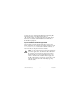
You can connect single-ended voltage signals to the NI 9201/9221. Connect the positive lead of the voltage signal to AI. Connect the ground signal to COM. Refer to Figure 3 for an illustration of connecting a single-ended voltage signal to the NI 9201/9221. AI Voltage Source + – COM NI 9201/9221 Figure 4.
screw-terminal connector or use the NI 9932 backshell kit to protect the connections. Refer to Figure 5 for an illustration of using ferrules. Refer to Figure 1 for an illustration of the NI 9932 connector backshell. Figure 5. 10-Terminal Detachable Screw-Terminal Connector with Ferrule © National Instruments Corp.
Sleep Mode This module supports a low-power sleep mode. Support for sleep mode at the system level depends on the chassis that the module is plugged into. Refer to the chassis manual for information about support for sleep mode. If the chassis supports sleep mode, refer to the software help for information about enabling sleep mode. Visit ni.com/info and enter cseriesdoc for information about C Series documentation. Typically, when a system is in sleep mode, you cannot communicate with the modules.
Input Characteristics Number of channels.......................... 8 analog input channels ADC resolution................................. 12 bits Type of ADC..................................... Successive approximation register (SAR) Sample rate (aggregate) Maximum Sample Rate (R Series Expansion Chassis) Maximum Sample Rate (All Other Chassis) NI 9201, single channel 475 kS/s 800 kS/s NI 9201, scanning 475 kS/s 500 kS/s NI 9221 475 kS/s 800 kS/s Module Input range NI 9201.....................
Operating voltage ranges1 Measurement Voltage, Channel-to-COM Maximum Voltage, Channel-to-Earth Ground or COM-to-Earth Ground Module Min (V) Typ (V) Max (V) Screw Terminal DSUB NI 9201 ±10.3 ±10.53 ±10.8 250 Vrms ±60 VDC NI 9221 ±61.4 ±62.50 ±63.8 Overvoltage protection (channel-to-COM) ............................ ±100 V 1 Refer to the Safety Guidelines section for more information about safe operating voltages. NI 9201/9221 14 ni.
NI 9201 accuracy (excludes noise) Percent of Reading (Gain Error) Percent of Range* (Offset Error) Calibrated typ (25 °C, ±5 °C) ±0.04% ±0.07% Calibrated max (–40 to 70 ºC) ±0.25% ±0.25% Uncalibrated typ (25 °C, ±5 °C) ±0.26% ±0.46% Uncalibrated max (–40 to 70 ºC) ±0.67% ±1.25% Measurement Conditions * Range equals 10.53 V © National Instruments Corp.
NI 9221 accuracy (excludes noise) Percent of Reading (Gain Error) Percent of Range* (Offset Error) Calibrated typ (25 °C, ±5 °C) ±0.04% ±0.07% Calibrated max (–40 to 70 ºC) ±0.25% ±0.25% Uncalibrated typ (25 °C, ±5 °C) ±0.26% ±0.43% Uncalibrated max (–40 to 70 ºC) ±0.67% ±1.06% Measurement Conditions * Range equals 62.50 V Stability Gain drift .................................... ±34 ppm/°C Offset drift NI 9201 ................................ ±100 μV/°C NI 9221 ............................
Input impedance Resistance................................... 1 MΩ Capacitance ................................ 5 pF Input noise (code-centered) RMS ........................................... 0.7 LSBrms Peak-to-peak............................... 5 LSB No missing codes.............................. 12 bits DNL .................................................. –0.9 to 1.5 LSB INL.................................................... ±1.5 LSB Crosstalk (at 10 kHz) ........................
MTBF ............................................... 1,485,465 hours at 25 °C; Bellcore Issue 6, Method 1, Case 3, Limited Part Stress Method Note Contact NI for Bellcore MTBF specifications at other temperatures or for MIL-HDBK-217F specifications. Power Requirements Power consumption from chassis Active mode ............................... 550 mW max Sleep mode ................................. 1 mW max Thermal dissipation (at 70 °C) Active mode ............................... 600 mW max Sleep mode .....
Physical Characteristics If you need to clean the module, wipe it with a dry towel. Screw-terminal wiring ...................... 12 to 24 AWG copper conductor wire with 10 mm (0.39 in.) of insulation stripped from the end Ferrules ............................................. 0.25 mm2 to 2.5 mm2 Torque for screw terminals ............... 0.5 to 0.6 N · m (4.4 to 5.3 lb · in.) Weight NI 9201/9221 with screw terminal .................... 150 g (5.3 oz) NI 9201/9221 with DSUB.......... 145 g (5.
NI 9201/9221 with Screw Terminal Isolation Voltages Channel-to-channel........................... No isolation between channels Channel-to-earth ground Continuous ................................. 250 Vrms, Measurement Category II Withstand.................................... 2,300 Vrms, verified by a 5 s dielectric withstand test Measurement Category II is for measurements performed on circuits directly connected to the electrical distribution system.
NI 9201/9221 with DSUB Isolation Voltages Channel-to-channel........................... No isolation between channels Channel-to-earth ground Continuous ................................. 60 VDC, Measurement Category I Withstand.................................... 1,000 Vrms, verified by a 5 s dielectric withstand test Measurement Category I is for measurements performed on circuits not directly connected to the electrical distribution system referred to as MAINS voltage.
Safety Standards This product is designed to meet the requirements of the following standards of safety for electrical equipment for measurement, control, and laboratory use: • IEC 61010-1, EN 61010-1 • UL 61010-1, CSA 61010-1 Note For UL and other safety certifications, refer to the product label or visit ni.com/certification, search by module number or product line, and click the appropriate link in the Certification column. Hazardous Locations U.S. (UL) ..........................................
Environmental National Instruments C Series modules are intended for indoor use only but may be used outdoors if installed in a suitable enclosure. Refer to the manual for the chassis you are using for more information about meeting these specifications. Operating temperature (IEC 60068-2-1, IEC 60068-2-2) ..... –40 to 70 °C Storage temperature (IEC 60068-2-1, IEC 60068-2-2) ..... –40 to 85 °C Ingress protection.............................. IP 40 Operating humidity (IEC 60068-2-56).........................
Shock and Vibration To meet these specifications, you must panel mount the system. If you are using the NI 9201/9221 with screw terminal, you also must either affix ferrules to the ends of the terminal wires or use the NI 9932 backshell kit to protect the connections. Operating vibration Random (IEC 60068-2-64)......... 5 grms, 10 to 500 Hz Sinusoidal (IEC 60068-2-6) ....... 5 g, 10 to 500 Hz Operating shock (IEC 60068-2-27)....
Note For EMC compliance, operate this device with shielded cabling. CE Compliance This product meets the essential requirements of applicable European directives, as amended for CE markings, as follows: • 2006/95/EC; Low-Voltage Directive (safety) • 2004/108/EC; Electromagnetic Compatibility Directive (EMC) Note Refer to the Declaration of Conformity (DoC) for this product for any additional regulatory compliance information. To obtain the DoC for this product, visit ni.
For additional environmental information, refer to the NI and the Environment Web page at ni.com/environment. This page contains the environmental regulations and directives with which NI complies, as well as other environmental information not included in this document. Waste Electrical and Electronic Equipment (WEEE) EU Customers At the end of their life cycle, all products must be sent to a WEEE recycling center.
Calibration You can obtain the calibration certificate and information about calibration services for the NI 9201/9221 at ni.com/ calibration. Calibration interval ........................... 1 year Where to Go for Support The National Instruments Web site is your complete resource for technical support. At ni.com/support you have access to everything from troubleshooting and application development self-help resources to email and phone assistance from NI Application Engineers.
Canada 800 433 3488, China 86 21 5050 9800, Czech Republic 420 224 235 774, Denmark 45 45 76 26 00, Finland 358 (0) 9 725 72511, France 01 57 66 24 24, Germany 49 89 7413130, India 91 80 41190000, Israel 972 3 6393737, Italy 39 02 41309277, Japan 0120-527196, Korea 82 02 3451 3400, Lebanon 961 (0) 1 33 28 28, Malaysia 1800 887710, Mexico 01 800 010 0793, Netherlands 31 (0) 348 433 466, New Zealand 0800 553 322, Norway 47 (0) 66 90 76 60, Poland 48 22 3390150, Portugal 351 210 311 210, Russia 7 495 783 6851,