Computer-Based Instruments NI 4050 User Manual Digital Multimeter Card for PCMCIA NI 4050 User Manual March 2000 Edition Part Number 321427C-01
Worldwide Technical Support and Product Information www.ni.
Important Information Warranty The NI 4050 is warranted against defects in materials and workmanship for a period of one year from the date of shipment, as evidenced by receipts or other documentation. National Instruments will, at its option, repair or replace equipment that proves to be defective during the warranty period. This warranty includes parts and labor.
Compliance FCC/Canada Radio Frequency Interference Compliance* Determining FCC Class The Federal Communications Commission (FCC) has rules to protect wireless communications from interference. The FCC places digital electronics into two classes. These classes are known as Class A (for use in industrialcommercial locations only) or Class B (for use in residential or commercial locations). Depending on where it is operated, this product could be subject to restrictions in the FCC rules.
• • Connect the equipment into an outlet on a circuit different from that to which the receiver is connected. Consult the dealer or an experienced radio/TV technician for help. Canadian Department of Communications This Class B digital apparatus meets all requirements of the Canadian Interference-Causing Equipment Regulations. Cet appareil numérique de la classe B respecte toutes les exigences du Règlement sur le matériel brouilleur du Canada.
Conventions The following conventions are used in this manual: » The » symbol leads you through nested menu items and dialog box options to a final action. The sequence File»Page Setup»Options directs you to pull down the File menu, select the Page Setup item, and select Options from the last dialog box. This icon denotes a note, which alerts you to important information. This icon denotes a caution, which advises you of precautions to take to avoid injury, data loss, or a system crash.
Contents Chapter 1 Taking Measurements with the NI 4050 Cable and Probes ...........................................................................................................1-1 Introduction to the VirtualBench-DMM Soft Front Panel.............................................1-3 Use the Soft Front Panel ................................................................................................1-5 Measure DC and AC Voltage..........................................................................
Contents Appendix A Specifications Appendix B Technical Support Resources Glossary Index Figures Figure 1-1. Figure 1-2. Figure 1-3. Figure 1-4. Figure 1-5. Figure 1-6. Figure 1-7. Figure 1-8. Installing the NI 4050 and Cables......................................................... 1-2 NI-DMM Soft Front Panel.................................................................... 1-3 Digits of Precision.................................................................................
Taking Measurements with the NI 4050 1 Thank you for buying a National Instruments 4050 digital multimeter card. A system based on the NI 4050 offers the flexibility, performance, and size that makes it ideal for service, repair, and manufacturing as well as for use in industrial and laboratory environments. The NI 4050, used in conjunction with your computer, is a versatile, cost-effective platform for high-resolution measurements. For the most current versions of manuals and example programs, visit www.
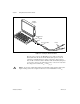
Chapter 1 Taking Measurements with the NI 4050 Portable Computer PCMCIA Slot NI 4050 Accessory Cable Probes Figure 1-1. Installing the NI 4050 and Cables The test probes connect to the NI 4050 accessory cable via shrouded banana jacks. The shrouds around the banana jacks prevent you from contacting potentially hazardous voltages connected to the test probes.
Chapter 1 Taking Measurements with the NI 4050 Introduction to the VirtualBench-DMM Soft Front Panel The following sections explain how to make connections to your NI 4050 and take simple measurements using the VirtualBench-DMM, as shown in Figure 1-2. To launch the soft front panel, select Start»Programs» National Instruments DMM»Soft Front Panel. Figure 1-2. NI-DMM Soft Front Panel The following text describes the options available on the soft front panel.
Chapter 1 Taking Measurements with the NI 4050 The Function selector allows you select a measurement mode. Select Edit»Settings and click on the tabs for Current and Resistance or Temperature to control the data type acquired by VirtualBench-DMM. DC volts measures the DC component of a voltage signal. AC volts measures the AC component of a voltage signal. DC current measures the DC component of a current source. AC current measures the AC component of a current source.
Chapter 1 Taking Measurements with the NI 4050 % selects the percentage calculation. VirtualBench-DMM expresses the displayed reading as a percent deviation from the reference value entered in the Math Settings. Refer to Help»Online Reference, Math Settings topic for more information about dB, dBm, mX+B, and percentage calculations. The log button enables data logging. To configure the datalog file and log interval, select Edit»Settings.
Chapter 1 Taking Measurements with the NI 4050 The NI 4050 is protected against damage from voltages within ±250 VDC or 250 Vrms in all ranges. You should never apply voltages above these levels to the inputs. HI HI + – 250 V MAX. DC Voltage Source AC Voltage Source 250 V MAX. LO LO Figure 1-4. Connecting Probes for Voltage Measurement 2. 3.
Chapter 1 Taking Measurements with the NI 4050 HI 250 V MAX. Resistor LO Figure 1-5. Connections for Resistance Measurement 2. Select 2-wire resistance mode. 3. Select the range for your measurement—200 Ω, 2 kΩ, 20 kΩ, 200 kΩ, 2 MΩ, 200 MΩ, or autorange. The value indicator indicates the resistance measured. See the 2-Wire Resistance Measurements section of Chapter 2, NI 4050 Operation, for more information on 2-wire resistance measurements.
Chapter 1 Taking Measurements with the NI 4050 2. Select diode mode. 3. Select the range for your measurement. Only the 2 V range is available for diode measurement. The value indicator will indicate the voltage drop measured. If the display indicates 2.200 VDC, the diode is either reverse biased or defective. See the Diode Measurements section of Chapter 2, NI 4050 Operation, for more information on diode measurements.
Chapter 1 Taking Measurements with the NI 4050 Measure Temperature You can measure temperature using common temperature transducers such as resistive temperature devices (RTD) and thermistors. You can measure transducers in the 2-wire resistance mode, as shown in Figure 1-8. Although the soft front panel does not support temperature measurements, you can convert and scale the transducer value to temperature programmatically through software.
2 NI 4050 Operation This chapter contains safety instructions, measurement fundamentals and concerns, and scanning information. Safety Instructions Cautions To avoid personal injury or damage to electronic equipment, observe the following: Do not operate this instrument in an explosive atmosphere or where there may be flammable gases or fumes. Equipment described in this document must be used in an Installation Category II environment per IEC 664.
Chapter 2 NI 4050 Operation Measurement Fundamentals Warm Up The required warm-up time for the NI 4050 is 30 minutes. This warm-up time is important because measurements made with the NI 4050 multimeter can change with temperature. This change is called a thermal drift and affects your accuracy. To minimize the effects of thermal drift and ensure the specified accuracies, take all measurements after the NI 4050 has had a chance to fully warm up.
Chapter 2 NI 4050 Operation Input Ranges The NI 4050 has five input ranges available for measuring DC voltages. These ranges are ±20 mV, ±200 mV, ±2.0 V, ±25V, and ±250 V. Each range has a 10% overrange, except for the 250 V range. The 250 V and 25 V input ranges have a 1 MΩ input impedance; the 2 V, 200 mV, and 20 mV ranges have an input impedance greater than 1 GΩ. Take these values into consideration when measuring high-impedance sources.
Chapter 2 NI 4050 Operation Thermal EMF Thermal EMFs, or thermoelectric potentials, are voltages generated at the junctions of dissimilar metals and are functions of temperature. Thermal EMFs in a circuit under test can cause higher than expected offsets that change with temperature. Noise Rejection The NI 4050 filters out AC voltages in the DC voltage measurement ranges.
Chapter 2 NI 4050 Operation HI Measured Voltage Vm + Input VΩ – Source Voltage Vs at 60 Hz LO N MRR – -------------------- 20 Vm = Vs × 10 Figure 2-2. Normal Mode Measurement Effects If you are measuring signals in the presence of large normal mode voltages, consult Appendix A, Specifications, to calculate the additional error to your system. Use the equation in Figure 2-2 to calculate the voltage error due to normal mode voltage.
Chapter 2 NI 4050 Operation HI Measured Voltage Vm + Input VΩ + – Source Voltage Vs + – Common Voltage Vc – LO –CMRR -------------------V 20 Verror = -----s- + Vc × 10 2 Vm = Vs + Verror Figure 2-3. Common Mode Measurement Effects Using the equation in Figure 2-3, you can calculate the voltage error due to the common mode voltage.
Chapter 2 NI 4050 Operation components and then measures the RMS value of the AC component. This method lets you measure a small AC signal in the presence of a large DC offset. Input Ranges The NI 4050 has five input ranges available for measuring AC voltages. These ranges are 20 mVrms, 200 mVrms, 2.0 Vrms, 25 Vrms, and 250 Vrms. The impedance in each of these ranges is a 0.068 µF capacitor followed by 1 MΩ. When the NI 4050 is powered off, the 250 V, 25 V, and 2 V input ranges have a 0.
Chapter 2 NI 4050 Operation These additional errors are shown in Appendix A, Specifications. While the NI 4050 is characterized and specified over the 20 Hz to 25 kHz frequency range, measurements outside of this range can still be made with decreased accuracy. Resistance Measurements 2-Wire Resistance Measurements The NI 4050 measures 2-wire resistance by passing a current through the device under test and reading the resulting voltage drop through the same connections, as illustrated in Figure 2-4.
Chapter 2 NI 4050 Operation In the extended ohms range, the NI 4050 adds a 1 MΩ resistor in parallel with the test resistor, and then calculates the value of the resistor being tested. The test current for the 200 Ω, 2.0 kΩ, and 20 kΩ ranges is 100 µA. The test current for the 200 kΩ, 2 MΩ, and 200 MΩ ranges is 1 µA. Continuity Measurements Many traditional multimeters can take continuity measurements, which test for the presence or absence of continuity between the two test probes.
A Specifications This appendix lists the specifications of the NI 4050. These specifications are guaranteed between 15 and 35 °C unless otherwise specified. DC Voltage Accuracy (% of reading ± µV) Range 24 Hour (25 °C ± 1 °C) 90 Day (25 °C ± 10 °C) 1 Year (25° C ± 10 °C) Temperature Coefficient (% of Reading/ °C ± µV/ °C) 250.000 V 0.0032% ± 4.9 mV 0.021% ± 49 mV 0.024% ± 49 mV 0.0017% ± 4800 µV 25.0000 V 0.0032% ± 4.9 mV 0.021% ± 49 mV 0.024% ± 49 mV 0.0017% ± 4800 µV 2.00000 V 0.
Appendix A Specifications DC Current Accuracy (% of reading ± µA) DC current measurements require the use of the CSM current shunt modules. Range 24 Hour (25 °C ± 1 °C) 90 Day (25 °C ± 10 °C) 1 Year (25 °C ± 10 °C) Temperature Coefficient (% of Reading/°C ± µA/°C) 200.000 mA* 0.1% ± 27 µA 0.14% ± 250 µA 0.15% ± 250 µA 0.0035% ± 25 µA mA* 0.1% ± 27 µA 0.14% ± 250 µA 0.15% ± 250 µA 0.0035% ± 25 µA 10.0000 A** 0.02% ± 4 mA 0.035% ± 26 mA 0.035% ± 26 mA 0.007% ± 2.5 mA 20.
Appendix A Specifications AC Voltage Accuracy (% of reading ± mV) Range 24 Hour (25 °C ± 1 °C) 90 Day (25 °C ± 10 °C) 1 Year (25 °C ± 10 °C) Temperature Coefficient (% of Reading/°C ± mV/°C) 250.000 V 0.6% ± 500 mV 0.62% ± 680 mV 0.62% ± 680 mV 0.007% ± 20 mV 25.0000 V 0.3% ± 30 mV 0.32% ± 210 mV 0.32% ± 210 mV 0.007% ± 20 mV 2.00000 V 0.4% ± 3 mV 0.42% ± 21 mV 0.42% ± 21 mV 0.019% ± 2 mV 200.000 mV 0.3% ± 0.22 mV 0.32% ± 1.20 mV 0.32% ± 1.20 mV 0.007% ± 0.110 mV 20.0000 mV 0.
Appendix A Specifications AC Current Accuracy (% of reading ± mA) AC current measurements require the use of the CSM current shunt module. Range 24 Hour (25 °C ± 1 °C) 90 Day (25 °C ± 10 °C) 1 Year (25 °C ± 10 °C) Temperature Coefficient (% of Reading/°C ± mA/°C) 200.000 mA* 0.45% ± 0.22 mA 0.47% ± 1.2 mA 0.47% ± 1.2 mA 0.007% ± 0.110 mA mA* 0.35% ± 110 µA 0.37% ± 170 µA 0.37% ± 170 µA 0.019% ± 0.120 mA 0.3% ± 22 mA 0.32% ± 120 mA 0.32% ± 120 mA 0.026% ± 11 mA 20.0000 10.
Appendix A Specifications Resistance Accuracy (% of reading ± Ω) 24 Hour (25 °C ± 1 °C) 90 Day (25 °C ± 10 °C) 1 Year (25 °C ± 10 °C) Temperature Coefficient (% of Reading/°C ± Ω/°C) Extended Ohm (> 2 MΩ) 0.1% ± 6 kΩ 0.1% ± 60 kΩ 0.1% ± 60 kΩ 0.0072% ± 6 kΩ 2.00000 MΩ 0.012% ± 55 Ω 0.077% ± 370 Ω 0.080% ± 20 Ω 0.0072% ± 35 Ω 200.000 kΩ 0.012% ± 37 Ω 0.077% ± 350 Ω 0.080% ± 2 Ω 0.0072% ± 35 Ω 20.0000 kΩ 0.006% ± 0.5 Ω 0.024% ± 4 Ω 0.027% ± 4 Ω 0.0020% ± 0.40 Ω 2.00000 kΩ 0.
Appendix A Specifications General Specifications Settling time............................................Affected by source impedance and input signal changes Warm-up time.........................................30 minutes for measurements accurate within specifications Bus type ..................................................PCMCIA, slave Altitude ...................................................Up to 2,000 m; at higher altitudes the installation category must be derated Working voltage ............
Technical Support Resources B This appendix describes the comprehensive resources available to you in the Technical Support section of the National Instruments Web site and provides technical support telephone numbers for you to use if you have trouble connecting to our Web site or if you do not have internet access. NI Web Support To provide you with immediate answers and solutions 24 hours a day, 365 days a year, National Instruments maintains extensive online technical support resources.
Appendix B Technical Support Resources Software-Related Resources • Instrument Driver Network—A library with hundreds of instrument drivers for control of standalone instruments via GPIB, VXI, or serial interfaces. You also can submit a request for a particular instrument driver if it does not already appear in the library. • Example Programs Database—A database with numerous, non-shipping example programs for National Instruments programming environments.
Glossary Prefix Meanings Value p- pico- 10 –12 n- nano- 10 –9 µ- micro- 10 – 6 m- milli- 10 –3 k- kilo- 10 3 M- mega- 10 6 G- giga- 10 9 Numbers/Symbols % percent + positive of, or plus – negative of, or minus / per ° degree ± plus or minus Ω ohm A A amperes AC alternating current AC coupled the passing of a signal through a filter network that removes the DC component of the signal A/D analog-to-digital © National Instruments Corporation G-1 NI 4050 User Manu
Glossary ADC analog-to-digital converter—an electronic device, often an integrated circuit, that converts an analog voltage to a digital number ADC resolution the resolution of the ADC, which is measured in bits. An ADC with16 bits has a higher resolution, and thus a higher degree of accuracy, than a 12-bit ADC.
Glossary CompactPCI refers to the core specification defined by the PCI Industrial Computer Manufacturer’s Group (PICMG) conversion device device that transforms a signal from one form to another. For example, analog-to-digital converters (ADCs) for analog input, digital-to-analog converters (DACs) for analog output, digital input or output ports, and counter/timers are conversion devices.
Glossary dielectric absorption a parasitic phenomenon related to capacitors that can cause unexpectedly long settling times in circuits using capacitors with poor dielectric absorption specifications differential input an analog input consisting of two terminals, both of which are isolated from computer ground, whose difference is measured DMM digital multimeter DNL differential nonlinearity—a measure in LSB of the worst-case deviation of code widths from their ideal value of 1 LSB double insulated
Glossary H harmonics multiples of the fundamental frequency of a signal half-power bandwidth the frequency range over which a circuit maintains a level of at least –3 dB with respect to the maximum level hardware the physical components of a computer system, such as the circuit boards, plug-in boards, chassis, enclosures, peripherals, cables, and so on Hz hertz—per second, as in cycles per second or samples per second I Iex excitation current IEC International Electrotechnical Commission IEEE
Glossary ISA industry standard architecture isolation a type of signal conditioning in which you isolate the transducer signals from the computer for safety purposes. This protects you and your computer from large voltage spikes and makes sure the measurements from the DAQ device are not affected by differences in ground potentials.
Glossary P PCI Peripheral Component Interconnect—a high-performance expansion bus architecture originally developed by Intel to replace ISA and EISA; it is achieving widespread acceptance as a standard for PCs and workstations and offers a theoretical maximum transfer rate of 132 Mbytes/s peak value the absolute maximum or minimum amplitude of a signal (AC + DC) PXI PCI eXtensions for Instrumentation.
Glossary S s seconds S samples sense in four-wire resistance the sense measures the voltage across the resistor being excited by the excitation current settling time the amount of time required for a voltage to reach its final value within specified limits S/s samples per second—used to express the rate at which an instrument samples an analog signal system noise a measure of the amount of noise seen by an analog circuit or an ADC when the analog inputs are grounded T temperature coefficient t
Glossary V V volts VAC volts alternating current VDC volts direct current Verror voltage error VI virtual instrument—(1) a combination of hardware and/or software elements, typically used with a PC, that has the functionality of a classic stand-alone instrument (2) a LabVIEW software module (VI), which consists of a front panel user interface and a block diagram program VMC voltmeter complete signal Vrms volts, root mean square value Vsense the voltage that is created across the device under
Index A diode measurement circuit (figure), 2-9 description, 2-9 using VirtualBench-DMM Soft Front panel, 1-7 to 1-8 diode testing specifications, A-5 AC current specifications, A-4 AC voltage measurement, 2-6 to 2-8 AC offset voltage, 2-7 frequency response, 2-7 to 2-8 input ranges, 2-7 using VirtualBench-DMM Soft Front panel, 1-5 to 1-6 AC voltage specifications, A-3 E effective common mode rejection, 2-6 environment specifications, A-6 C cables and probes, 1-1 to 1-2 installing, 1-1 to 1-2 overview,
Index fundamentals of measurement grounding, 2-2 selecting resolution, 2-2 warm-up time, 2-2 noise rejection AC voltage specifications, A-3 DC voltage measurement, 2-4 to 2-6 common mode rejection, 2-6 to 2-7 effective common mode rejection, 2-6 normal mode rejection, 2-4 to 2-5 DC voltage specifications, A-1 normal mode rejection, 2-4 to 2-5 using VirtualBench-DMM Soft Front panel, 1-5 to 1-6 current, 1-8 DC voltage, 2-2 to 2-6 common mode rejection, 2-6 to 2-7 effective common mode rejection, 2-6 input
Index S V safety instructions, 2-1 soft front panel. See VirtualBench-DMM Soft Front panel.