DAQ NI 6115/6120 User Manual Multifunction I/O Devices for PCI/PXI/CompactPCI Bus Computers NI 6115/6120 User Manual August 2002 Edition Part Number 322812B-01
Support Worldwide Technical Support and Product Information ni.
Important Information Warranty The NI PCI-6115, NI PXI-6115, NI PCI-6120, and NI PXI-6120 devices are warranted against defects in materials and workmanship for a period of one year from the date of shipment, as evidenced by receipts or other documentation. National Instruments will, at its option, repair or replace equipment that proves to be defective during the warranty period. This warranty includes parts and labor.
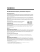
Compliance FCC/Canada Radio Frequency Interference Compliance Determining FCC Class The Federal Communications Commission (FCC) has rules to protect wireless communications from interference. The FCC places digital electronics into two classes. These classes are known as Class A (for use in industrial-commercial locations only) or Class B (for use in residential or commercial locations). Depending on where it is operated, this product could be subject to restrictions in the FCC rules.
Canadian Department of Communications This Class B digital apparatus meets all requirements of the Canadian Interference-Causing Equipment Regulations. Cet appareil numérique de la classe B respecte toutes les exigences du Règlement sur le matériel brouilleur du Canada. Compliance to EU Directives Readers in the European Union (EU) must refer to the Manufacturer’s Declaration of Conformity (DoC) for information* pertaining to the CE Mark compliance scheme.
Contents About This Manual Conventions ...................................................................................................................xi National Instruments Documentation ............................................................................xii Related Documentation..................................................................................................xiii Chapter 1 Introduction About the NI 6115/6120 .....................................................................
Contents Timing Signal Routing .................................................................................................. 3-10 Programmable Function Inputs ....................................................................... 3-12 Device and RTSI Clocks................................................................................. 3-12 RTSI Triggers .................................................................................................
Contents GPCTR1_OUT Signal ......................................................................4-36 GPCTR1_UP_DOWN Signal ...........................................................4-37 FREQ_OUT Signal ...........................................................................4-38 Field Wiring Considerations ..........................................................................................4-39 Chapter 5 Calibration Loading Stored Calibration Constants ............................................
About This Manual This manual describes the electrical and mechanical aspects of the NI 6115/6120 and contains information concerning its operation and programming. The NI 6115/6120 family includes the following devices: • NI PCI-6115 • NI PXI-6115 • NI PCI-6120 • NI PXI-6120 The NI 6115/6120 is a high-performance multifunction analog, digital, and timing I/O data acquisition (DAQ) device for PXI and PCI bus computers.
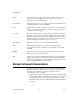
About This Manual bold Bold text denotes items that you must select or click on in the software, such as menu items and dialog box options. Bold text also denotes parameter names and hardware labels. CompactPCI CompactPCI refers to the core specification defined by the PCI Industrial Computer Manufacturer’s Group (PICMG). italic Italic text denotes variables, emphasis, a cross reference, or an introduction to a key concept.
About This Manual • DAQ hardware documentation—This documentation has detailed information about the DAQ hardware that plugs into or is connected to the computer. Use this documentation for hardware installation and configuration instructions, specification information about the DAQ hardware, and application hints. • Software documentation—You may have both application software and NI-DAQ documentation. NI application software includes LabVIEW and Measurement Studio.
1 Introduction This chapter describes the NI 6115/6120, lists what you need to get started, describes the optional software and optional equipment, and explains how to unpack the device. About the NI 6115/6120 Thank you for buying an NI 6115/6120. The NI 6115/6120 is a Plug and Play multifunction analog, digital, and timing I/O device for PXI and PCI bus computers.
Chapter 1 Introduction you do not need the RTSI cable for system triggering and timing on the PXI. In addition, a phase-locked loop (PLL) circuit accomplishes the synchronization of multiple NI PXI-6115/6120 devices or other PXI devices which support PLL synchronization by allowing these devices to all lock to the same reference clock present on the PXI backplane. Refer to the Phase-Locked Loop Circuit section of Chapter 3, Hardware Overview, for more information.
Chapter 1 Introduction Table 1-1. NI PXI-6115/6120 J2 Pin Assignment NI PXI-6115/6120 Signal PXI Pin Name PXI J2 Pin Number RTSI<0..5> PXI Trigger<0..5> B16, A16, A17, A18, B18, C18 RTSI 6 Star D17 RTSI Clock PXI Trigger 7 E16 Reserved LBL<0..12> C20, E20, A19, C19 Reserved LBR<0..
Chapter 1 Introduction Software Programming Choices When programming National Instruments DAQ hardware, you can use an NI application development environment (ADE) or other ADEs. In either case, you use NI-DAQ. NI-DAQ NI-DAQ, which shipped with the NI 6115/6120, has an extensive library of functions that you can call from the ADE. These functions allow you to use all the features of the device.
Chapter 1 Conventional Programming Environment Introduction LabVIEW, LabWindows/CVI, Measurement Studio, or VI Logger NI-DAQ Driver Software DAQ Hardware Personal Computer or Workstation Figure 1-1. The Relationship Among the Programming Environment, NI-DAQ, and the Hardware To download a free copy of the most recent version of NI-DAQ, click Download Software at ni.com.
Chapter 1 Introduction DAQ hardware. These ActiveX controls provide a high-level programming interface for building virtual instruments (VIs). For Visual C++ developers, Measurement Studio offers a set of Visual C++ classes and tools to integrate those classes into Visual C++ applications. The ActiveX controls and classes are available with Measurement Studio and the NI-DAQ software. VI Logger is an easy-to-use yet flexible tool specifically designed for data logging applications.
Chapter 1 Introduction • Route the analog lines separately from the digital lines. • When using a cable shield, use separate shields for the analog and digital halves of the cable. Failure to do so results in noise coupling into the analog signals from transient digital signals. Mating connectors and a backshell kit for making custom 68-pin cables are available from NI.
Chapter 1 Introduction Safety Information The following section contains important safety information that you must follow when installing and using the product. Do not operate the product in a manner not specified in this document. Misuse of the product can result in a hazard. You can compromise the safety protection built into the product if the product is damaged in any way. If the product is damaged, return it to National Instruments for repair.
Chapter 1 Introduction The following is a description of installation categories: • Installation Category I is for measurements performed on circuits not directly connected to MAINS1. This category is a signal level such as voltages on a printed wire board (PWB) on the secondary of an isolation transformer. Examples of Installation Category I are measurements on circuits not derived from MAINS and specially protected (internal) MAINS-derived circuits.
Chapter 1 Introduction Below is a diagram of a sample installation. NI 6115/6120 User Manual 1-10 ni.
Installing and Configuring the NI 6115/6120 2 This chapter explains how to install and configure the NI 6115/6120. Installing the Software Before you install the NI 6115/6120, complete the following steps to install the software: 1. Install the ADE, such as LabVIEW or Measurement Studio, according to the instructions on the CD and the release notes. 2. Install NI-DAQ according to the instructions on the CD and the DAQ Quick Start Guide included with the device.
Chapter 2 Installing and Configuring the NI 6115/6120 or bus master devices. NI recommends installing the NI PXI-6115/6120 in such a slot. Note The PXI specification requires all slots to support bus master devices, but the CompactPCI specification does not. If you install in a CompactPCI non-master slot, you must disable the onboard DMA controller using software. 3. Make sure there are no lighted LEDs on the chassis. If any are lit, wait until they go out before continuing the installation. 4.
Chapter 2 Installing and Configuring the NI 6115/6120 8. Replace the cover. 9. Plug in and power on the computer. The NI PCI-6115/6120 is now installed. You are now ready to configure the hardware and software. Configuring the Device Because of the NI standard architecture for data acquisition and the PCI bus specification, the NI 6115/6120 is completely software-configurable. Two types of configuration are performed on the NI 6115/6120: bus-related and data acquisition-related configuration.
3 Hardware Overview This chapter presents an overview of the hardware functions on the NI 6115/6120. Figures 3-1 and 3-2 provide block diagrams for the NI 6115 and NI 6120, respectively.
Hardware Overview CH0+ CH0– + AI CH0 Mux CH0 Amplifier – CH1+ CH1– + AI CH1 Mux CH1 Amplifier – CH2+ CH2– + AI CH2 Mux CH2 Amplifier – I/O Connector CH3+ CH3– CH0 16-Bit ADC AntiAliasing Filter CH1 16-Bit ADC AntiAliasing Filter CH2 16-Bit ADC 16 CH0 Latch Data (16) 16 CH1 Latch Data (16) 16 CH2 Latch Data (16) Control ADC FIFO + AI CH3 Mux AntiAliasing Filter AntiAliasing Filter CH3 Amplifier – CH3 16-Bit ADC CH3 Latch 16 Calibration Mux Data (32) Generic Bus Interface
Chapter 3 Hardware Overview Input Polarity and Input Range The NI 6115/6120 has bipolar inputs only. Bipolar input means that the midpoint of the input voltage range is centered at zero volts. You can independently configure each channel for a different input voltage range. The software-programmable gain on this device increases its overall flexibility by matching the input signal ranges to those that the ADC can accommodate.
Chapter 3 Hardware Overview Table 3-1. Input Range and Measurement Precision Precision1 Input Range 6115 (12-Bit) 6120 (16-Bit) –50 to +50 V2 –20 to +20 V –10 to +10 V –5 to +5 V –2 to +2 V –1 to +1V –500 to +500 mV –200 to +200 mV 24.4 mV 9.77 mV 4.88 mV 2.44 mV 977 µV 488 µV 244 µV 97.7 µV 1.53 mV 610 µV 305 µV 153 µV 61.0 µV 30.5 µV 15.3 µV 6.10 µV 1 The value of 1 least significant bit (LSB) of the ADC; that is, the voltage increment corresponding to a change of one count in the ADC count.
Chapter 3 Hardware Overview Analog Output The NI 6115/6120 supplies two channels of AO voltage at the I/O connector. The range is fixed at bipolar ±10 V. The AO channels on the NI 6115 contain 12-bit DACs that are capable of 4 MS/s for one channel or 2.5 MS/s for each of two channels. The NI 6120 DACs are 16-bit, and they have the same AO capabilities as the NI 6115. Refer to Appendix A, Specifications, for more detailed information about the AO capabilities of the NI 6115/6120.
Chapter 3 Hardware Overview Digital Data ADC Analog Input CH0 + PGIA – highValue ADC Analog Input CH1 + Analog Input CH2 + Analog Input CH3 + Trigger DAC PGIA – ADC Mux PGIA – Analog Trigger Circuit DAQ-STC ADC PGIA – AC Couple 10 k PFI0/TRIG1 lowValue Trigger DAC Figure 3-3. Analog Trigger Block Diagram for the NI 6115/6120 In below-low-level analog triggering mode, the trigger is generated when the signal value is less than lowValue, as shown in Figure 3-4. HighValue is unused.
Chapter 3 Hardware Overview highValue Trigger Figure 3-5. Above-High-Level Analog Triggering Mode In inside-region analog triggering mode, the trigger is generated when the signal value is between the lowValue and the highValue, as Figure 3-6 shows. highValue lowValue Trigger Figure 3-6.
Chapter 3 Hardware Overview In low-hysteresis analog triggering mode, the trigger is generated when the signal value is less than lowValue, with the hysteresis specified by highValue, as Figure 3-8 shows. highValue lowValue Trigger Figure 3-8. Low-Hysteresis Analog Triggering Mode The analog trigger circuit generates an internal digital trigger based on the AI signal and the user-defined trigger levels.
Chapter 3 fcutoff fNyquist Hardware Overview 4 fcutoff (2 fcutoff) Response of Analog Hardware Filters Response of Software Filters Figure 3-9. Effects of Hardware and Software Filtering on Antialiasing Phase-Locked Loop Circuit ♦ NI PXI-6115/6120 A phase-locked loop (PLL) circuit accomplishes the synchronization of multiple NI PXI-6115/6120 devices or other PXI devices which support PLL synchronization by allowing these devices to all lock to the same reference clock present on the PXI backplane.
Hardware Overview PXI Bus Chapter 3 60 MHz out synched to 10 MHZ backplane clock Phase Comp 10 MHz Div/10 + Div/60 – Loop Filter VCXO Figure 3-10. PLL Block Diagram Correlated Digital I/O The NI 6115/6120 contains eight lines of DIO for general-purpose use. You can software-configure groups of individual lines for either input or output. The NI 6115/6120 includes a FIFO for buffered operation.
Chapter 3 Hardware Overview configurable. For example, Figure 3-11 shows the signal routing multiplexer for controlling the STARTSCAN signal. RTSI Trigger <0..6> STARTSCAN PFI<0..9> Scan Interval Counter TC GPCTR0_OUT Figure 3-11. STARTSCAN Signal Routing This figure shows that STARTSCAN can be generated from a number of sources, including the external signals RTSI<0..6> and PFI<0..9> and the internal signals Scan Interval Counter TC and GPCTR0_OUT.
Chapter 3 Hardware Overview Programmable Function Inputs The 10 PFIs are connected to the signal routing multiplexer for each timing signal, and software can select one of the PFIs as the external source for a given timing signal. It is important to note that any PFI can be used as an input by any timing signal and that multiple timing signals can simultaneously use the same PFI. This flexible routing scheme reduces the need to change physical connections to the I/O connector for different applications.
Chapter 3 Hardware Overview In PCI, you can access all seven RTSI lines (RTSI<0..6>) through their RTSI cable. With the NI PXI-6115/6120, RTSI<0..5> connects to PXI Trigger <0..5>, respectively, through the NI PXI-6115/6120 backplane. In PXI, RTSI<6> connects to the PXI Star Trigger line, allowing the NI 6115/6120 to receive triggers from any Star Trigger controller plugged into slot 2 of the chassis. For more information on the Star Trigger, refer to the PXI Specification Revision 2.0.
Chapter 3 Hardware Overview DAQ-STC TRIG1 TRIG2 CONVERT* UPDATE* PXI Star (6) RTSI Switch PXI Bus Connector WFTRIG PXI Trigger (0..5) 6 GPCTR0_SOURCE GPCTR0_GATE GPCTR0_OUT STARTSCAN AIGATE SISOURCE UISOURSE GPCTR1_SOURCE GPCTR1_GATE PXI Trigger (7) Switch RTSI_OSC (20 MHz) Figure 3-13. PXI RTSI Bus Signal Connections Refer to the Connecting Timing Signals section of Chapter 4, Connecting Signals, for a description of the signals shown in Figures 3-12 and 3-13.
4 Connecting Signals This chapter describes how to connect input and output signals to the NI 6115/6120 using the device I/O connector. Table 4-1. I/O Connector Details Device with I/O Connector Number of Pins Cable for Connecting to 100-pin Accessories Cable for Connecting to 68-pin Accessories NI 6115, NI 6120 68 N/A SH6868 Shielded Cable, SH68-68-EP, R6868, SH68-68R1-EP I/O Connector Figure 4-1 shows the pin assignments for the 68-pin I/O connector on the NI 6115/6120.
Chapter 4 Connecting Signals ACH0– ACH1+ ACH1GND ACH2– ACH3+ ACH3GND NC NC NC NC NC NC DAC0OUT DAC1OUT NC DIO4 DGND DIO1 DIO6 DGND +5V OUTPUT DGND DGND PFI0/TRIG1 PFI1/TRIG2 DGND +5V OUTPUT DGND PFI5/UPDATE* PFI6/WFTRIG DGND PFI9/GPCTR0_GATE GPCTR0_OUT FREQ_OUT 34 33 32 31 30 29 28 27 26 25 24 23 22 21 20 19 18 17 16 15 14 13 12 11 10 9 8 7 6 5 4 3 2 1 68 67 66 65 64 63 62 61 60 59 58 57 56 55 54 53 52 51 50 49 48 47 46 45 44 43 42 41 40 39 38 37 36 35 ACH0+ ACH0GND ACH1– ACH2+ ACH2GND ACH3– NC NC NC N
Chapter 4 Connecting Signals I/O Connector Signal Descriptions Table 4-2. Signal Descriptions for I/O Connector Pins Signal Name Reference Direction Description — — Ground for Analog Input Channels 0 through 3—These pins are the bias current return point for pseudodifferential measurements. ACH<0..3>+ ACH<0..3>GND Input Analog Input Channels 0 through 3 (+)—These pins are routed to the (+) terminal of the respective channel amplifier and carry the input signal. ACH<0..3>– ACH<0..
Chapter 4 Connecting Signals Table 4-2. Signal Descriptions for I/O Connector Pins (Continued) Signal Name Reference Direction Description PFI0/TRIG1 DGND Input Output PFI0/Trigger 1—As an input, this is either a PFI or the source for the hardware analog trigger. PFI signals are explained in the Connecting Timing Signals section later in this chapter. The hardware analog trigger is explained in the Analog Trigger section of Chapter 3, Hardware Overview. As an output, this is the TRIG1 signal.
Chapter 4 Connecting Signals Table 4-2. Signal Descriptions for I/O Connector Pins (Continued) Signal Name Reference Direction Description PFI8/GPCTR0_SOURCE DGND Input Output PFI8/Counter 0 Source—As an input, this is a PFI. As an output, this is the GPCTR0_SOURCE signal. This signal reflects the actual source connected to the general-purpose counter 0. PFI9/GPCTR0_GATE DGND Input Output PFI9/Counter 0 Gate—As an input, this is a PFI. As an output, this is the GPCTR0_GATE signal.
Chapter 4 Connecting Signals Table 4-4. Analog I/O Summary for the NI 6120 Signal Type and Direction Impedance Input/ Output Protection (Volts) On/Off Source (mA at V) Sink (mA at V) Rise Time (ns) Bias ACH<0..3>+ AI 100 GΩ to GND ±42 V to GND — — — ±300 pA ACH<0..3>– AI 100 GΩ to GND ±42 V to GND — — — ±200 pA Differential Pair ACH<0..3>+ to ACH<0..
Chapter 4 Connecting Signals Source (mA at V) Sink (mA at V) Rise Time (ns) Table 4-5. Digital I/O Signal Summary (Continued) Signal Name Signal Type and Direction Impedance Input/ Output Protection (Volts) On/Off PFI3/GPCTR1_SOURCE DIO — VCC +0.5 3.5 at (VCC –0.4) 5 at 0.4 1.5 50 kΩ pu PFI4/GPCTR1_GATE DIO — VCC +0.5 3.5 at (VCC –0.4) 5 at 0.4 1.5 50 kΩ pu GPCTR1_OUT DO — — 3.5 at (VCC –0.4) 5 at 0.4 1.5 50 kΩ pu PFI5/UPDATE* DIO — VCC +0.5 3.5 at (VCC –0.4) 5 at 0.
Chapter 4 Connecting Signals source. You must tie the ground reference of a floating signal to the NI 6115/6120 AI ground to establish a local or onboard reference for the signal. Otherwise, the measured input signal varies as the source floats out of the common-mode input range.
Chapter 4 Connecting Signals Connections for Ground-Referenced Signal Sources Figures 4-2 and 4-3 show how to connect a ground-referenced signal source to a channel on the NI 6115 and NI 6120, respectively.
Chapter 4 Connecting Signals AC Coupling GroundReferenced Signal Source CommonMode Noise and Ground Potential + + ACH0+ Vs 100 pF* PGIA 1 M* – + – ACH0– Instrumentation Amplifier Vm + Measured – Voltage High-Frequency Common Mode Choke Vcm – ACH0GND *10 kΩ40 pf for ranges > ±10 V 50 Ω 0.1 µF Figure 4-3.
Chapter 4 Connecting Signals Connections for Nonreferenced or Floating Signal Sources Figures 4-4 and 4-5 show how to connect a floating signal source to a channel on the NI 6115 and NI 6120, respectively.
Chapter 4 Connecting Signals AC Coupling Floating Signal Source + + ACH0+ Vs 100 pF* PGIA 1 M* – Bias Current Return Paths Bias Resistor (see text) – ACH0– Instrumentation Amplifier Vm + Measured – Voltage High-Frequency Common Mode Choke *10 kΩ40 pf for ranges > ±10 V 50 Ω 0.1 µF ACH0GND I/O Connector Figure 4-5.
Chapter 4 Connecting Signals Like any amplifier, the common-mode rejection ratio (CMRR) of the PGIA is limited at high frequency. This limitation has been compensated for in the design of the NI 6115/6120 by using a common-mode choke on each channel. ♦ NI 6115 The purpose of the 10 nF capacitance on the ACH<0..3>– connection of the NI 6115 is to provide an impedance for this choke to work against at high frequency, thus improving the high-frequency CMRR.
Chapter 4 Connecting Signals Connecting Analog Output Signals The AO signals are DAC0OUT, DAC1OUT, and AOGND. DAC0OUT is the voltage output signal for AO channel 0. DAC1OUT is the voltage output signal for AO channel 1. AOGND is the ground-reference signal for the AO channels. AOGND is a hard ground. Figure 4-6 shows how to connect AO signals to the NI 6115/6120. DAC0OUT + Load Channel 0 VOUT 0 – AOGND – Load VOUT 1 DAC1OUT Channel 1 + Analog Output Channels NI 6115/6120 Figure 4-6.
Chapter 4 Connecting Signals Connecting Digital I/O Signals The DIO signals are DIO<0..7> and DGND. DIO<0..7> are the signals making up the DIO port, and DGND is the ground-reference signal for the DIO port. You can program groups of individual lines to be inputs or outputs. Exceeding the maximum input voltage ratings, which are listed in Table 4-3, can damage the NI 6115/6120 and the computer. NI is not liable for any damage resulting from such signal connections.
Chapter 4 Connecting Signals Figure 4-7 shows DIO<0..3> configured for digital input and DIO<4..7> configured for digital output. Digital input applications include receiving TTL signals and sensing external device states such as the switch state shown in Figure 4-7. Digital output applications include sending TTL signals and driving external devices such as the LED shown in Figure 4-7. Correlating DIO Signal Connections You can correlate DIO and AI/AO operations to the same clock on the NI 6115/6120.
Chapter 4 Connecting Signals CLK DI<7:4> DO<3:0> Figure 4-8. Clock Signal Driving DI and DO Signals Figure 4-9 shows a DIO operation driven by the AO Update signal on its rising edge. AO Update DIO Figure 4-9.
Chapter 4 Connecting Signals Figure 4-10 shows a DIO operation driven by an RTSI clock signal on its falling edge. RTSI DIO Figure 4-10. Falling-Edge RTSI Clock Signal Driving a DIO Signal Power Connections Two pins on the I/O connector supply +5 V from the computer power supply using a self-resetting fuse. The fuse resets automatically within a few seconds after the overcurrent condition is removed. These pins are referenced to DGND and can be used to power external digital circuitry.
Chapter 4 Connecting Signals The DAQ signals are explained in the DAQ Timing Connections section later in this chapter. The Waveform Generation Timing Connections section later in this chapter explains the waveform generation signals, and the General-Purpose Timing Signal Connections section later in this chapter explains the general-purpose timing signals. All digital timing connections are referenced to DGND.
Chapter 4 Connecting Signals Programmable Function Input Connections You can externally control 13 internal timing signals from the PFI pins. The source for each of these signals is software-selectable from any PFI when you want external control. This flexible routing scheme reduces the need to change the physical wiring to the device I/O connector for different applications requiring alternative wiring. You can individually enable each of the PFI pins to output a specific internal timing signal.
Chapter 4 Connecting Signals TRIG1 STARTSCAN CONVERT* 4 Scan Counter 3 2 1 0 Figure 4-12. Typical Posttriggered Acquisition Pretriggered data acquisition allows you to view data that is acquired before the trigger of interest in addition to data acquired after the trigger. Figure 4-13 shows a typical pretriggered DAQ sequence. The description for each signal shown in these figures appears later in this chapter.
Chapter 4 Connecting Signals Refer to Chapter 3, Hardware Overview, for more information on analog triggering. As an output, TRIG1 reflects the action that initiates a DAQ sequence even if another PFI is externally triggering the acquisition. The output is an active high pulse with a pulse width of 25 to 50 ns. This output is set to high-impedance at startup. Figures 4-14 and 4-15 show the timing requirements for TRIG1. tw Rising-Edge Polarity Falling-Edge Polarity tw = 10 ns minimum Figure 4-14.
Chapter 4 Connecting Signals selection for either rising or falling edge. The selected edge of TRIG2 initiates the posttriggered phase of a pretriggered DAQ sequence. In pretriggered mode, the TRIG1 signal initiates the acquisition. The scan counter indicates the minimum number of scans before TRIG2 can be recognized. After the scan counter decrements to zero, it is loaded with the number of posttrigger scans to acquire while the acquisition continues.
Chapter 4 Connecting Signals STARTSCAN Signal Any PFI pin can receive as an input the STARTSCAN signal, which is available as an output on the PFI7/STARTSCAN pin. Refer to Figures 4-21 and 4-22 for the relationship of STARTSCAN to the DAQ sequence. As an input, STARTSCAN is configured in the edge-detection mode. You can select any PFI pin as the source for STARTSCAN and configure the polarity selection for either rising or falling edge. The selected edge of STARTSCAN initiates a scan.
Chapter 4 Connecting Signals tw tw = 25 – 50ns a. Start of Scan Start Pulse CONVERT* STARTSCAN toff = 10 ns minimum toff b. Scan in Progress, Two Conversions per Scan Figure 4-19. STARTSCAN Output Signal Timing The CONVERT* pulses are masked off until the device generates STARTSCAN. If you are using internally generated conversions, the first CONVERT* appears when the onboard sample interval counter reaches zero.
Chapter 4 Connecting Signals CONVERT* Signal Any PFI pin can receive as an input the CONVERT* signal, which is available as an output on the PFI2/CONVERT* pin. Refer to Figures 4-23 and 4-24 for the relationship of CONVERT* to the DAQ sequence. As an input, CONVERT* is configured in the edge-detection mode. You can select any PFI pin as the source for CONVERT* and configure the polarity selection for either rising or falling edge. The selected edge of CONVERT* initiates an A/D conversion.
Chapter 4 Connecting Signals The ADC switches to hold mode within 20 ns of the selected edge. This hold-mode delay time is a function of temperature and does not vary from one conversion to the next. The sample interval counter on the NI 6115/6120 device normally generates CONVERT* unless you select some external source. The counter is started by the STARTSCAN signal and continues to count down and reload itself until the scan is finished.
Chapter 4 Connecting Signals Either the 20 MHz or 100 kHz internal timebase generates SISOURCE unless you select some external source. Figure 4-22 shows the timing requirements for SISOURCE. tp tw tw tp = 50 ns minimum tw = 23 ns minimum Figure 4-22. SISOURCE Signal Timing SCANCLK Signal SCANCLK is an output-only signal that generates a pulse with the leading edge occurring approximately 50 to 100 ns after an A/D conversion begins.
Chapter 4 Connecting Signals EXTSTROBE* Signal EXTSTROBE* is an output-only signal that generates either a single pulse or a sequence of eight pulses in the hardware-strobe mode. An external device can use this signal to latch signals or to trigger events. In the single-pulse mode, software controls the level of EXTSTROBE*. A 10 µs and a 1.2 µs clock are available for generating a sequence of eight pulses in the hardware-strobe mode. Note EXTSTROBE* cannot be enabled through NI-DAQ.
Chapter 4 Connecting Signals Figures 4-25 and 4-26 show the timing requirements for WFTRIG. tw Rising-Edge Polarity Falling-Edge Polarity tw = 10 ns minimum Figure 4-25. WFTRIG Input Signal Timing tw tw = 25 – 50 ns Figure 4-26. WFTRIG Output Signal Timing UPDATE* Signal Any PFI pin can receive as an input the UPDATE* signal, which is available as an output on the PFI5/UPDATE* pin. As an input, UPDATE* is configured in the edge-detection mode.
Chapter 4 Connecting Signals Figures 4-27 and 4-28 show the timing requirements for UPDATE*. tw Rising-Edge Polarity Falling-Edge Polarity tw = 10 ns minimum Figure 4-27. UPDATE* Input Signal Timing tw tw = 50 – 75 ns Figure 4-28. UPDATE* Output Signal Timing The DACs are updated within 100 ns of the leading edge. Separate the UPDATE* pulses with enough time that new data can be written to the DAC latches.
Chapter 4 Connecting Signals tp tw tw tp = 50 ns minimum tw = 10 ns minimum Figure 4-29. UISOURCE Signal Timing The maximum allowed frequency is 20 MHz, with a minimum pulse width of 10 ns high or low. There is no minimum frequency limitation. Either the 20 MHz or 100 kHz internal timebase normally generates UISOURCE unless you select some external source.
Chapter 4 Connecting Signals Figure 4-30 shows the timing requirements for GPCTR0_SOURCE. tp tw tw tp = 50 ns minimum tw = 10 ns minimum Figure 4-30. GPCTR0_SOURCE Signal Timing The maximum allowed frequency is 20 MHz, with a minimum pulse width of 10 ns high or low. There is no minimum frequency limitation. The 20 MHz or 100 kHz timebase normally generates GPCTR0_SOURCE unless you select some external source.
Chapter 4 Connecting Signals Figure 4-31 shows the timing requirements for GPCTR0_GATE. tw Rising-Edge Polarity Falling-Edge Polarity tw = 10 ns minimum Figure 4-31. GPCTR0_GATE Signal Timing in Edge-Detection Mode GPCTR0_OUT Signal This signal is available as an output on the GPCTR0_OUT pin. The GPCTR0_OUT signal reflects the terminal count (TC) of general-purpose counter 0. You have two software-selectable output options: pulse on TC and toggle output polarity on TC.
Chapter 4 Connecting Signals GPCTR0_UP_DOWN Signal This signal can be received as an input on the DIO6 pin and is not available as an output on the I/O connector. The general-purpose counter 0 counts down when this pin is at a logic low and count up when it is at a logic high. You can disable this input so that software can control the up-down functionality and leave the DIO6 pin free for general use.
Chapter 4 Connecting Signals GPCTR1_GATE Signal Any PFI pin can receive as an input the GPCTR1_GATE signal, which is available as an output on the PFI4/GPCTR1_GATE pin. As an input, GPCTR1_GATE is configured in edge-detection mode. You can select any PFI pin as the source for GPCTR1_GATE and configure the polarity selection for either rising or falling edge.
Chapter 4 Connecting Signals Figure 4-34 shows the timing requirements for GPCTR1_OUT. TC GPCTR1_SOURCE GPCTR1_OUT (Pulse on TC) GPCTR1_OUT (Toggle output on TC) Figure 4-35. GPCTR1_OUT Signal Timing GPCTR1_UP_DOWN Signal This signal can be received as an input on the DIO7 pin and is not available as an output on the I/O connector. General-purpose counter 1 counts down when this pin is at a logic low and counts up at a logic high.
Chapter 4 Connecting Signals The GATE and OUT signal transitions shown in Figure 4-36 are referenced to the rising edge of the SOURCE signal. This timing diagram assumes that the counters are programmed to count rising edges. The same timing diagram, but with the source signal inverted and referenced to the falling edge of the source signal, would apply when the counter is programmed to count falling edges.
Chapter 4 Connecting Signals Field Wiring Considerations Environmental noise can seriously affect the measurement accuracy of the NI 6115/6120 if you do not take proper care when running signal wires between signal sources and the device. The following recommendations apply mainly to AI signal routing, although they also apply to signal routing in general.
5 Calibration This chapter discusses the calibration procedures for the NI 6115/6120. NI-DAQ includes calibration functions for performing all of the steps in the calibration process. Calibration refers to the process of minimizing measurement and output voltage errors by making small circuit adjustments. On the NI 6115/6120, these adjustments take the form of writing values to onboard calibration DACs (CalDACs). Some form of device calibration is required for most applications.
Chapter 5 Calibration This method of calibration is not very accurate because it does not take into account the fact that the device measurement and output voltage errors can vary with time and temperature. It is better to self-calibrate when the device is installed in the environment in which it is used. Self-Calibration The NI 6115/6120 can measure and correct for almost all of its calibration-related errors without any external signal connections. NI-DAQ software provides a self-calibration method.
Chapter 5 Calibration To externally calibrate your device, be sure to use a very accurate external reference. The reference should be several times more accurate than the device itself. For a detailed calibration procedure for the NI 6115/6120, click Manual Calibration Procedures at ni.com/calibration.
A Specifications This appendix lists the specifications of the NI 6115/6120. These specifications are typical at 25 °C unless otherwise noted. Analog Input Input Characteristics Number of channels ............................... 4 pseudodifferential Type of ADC Resolution NI 6115 .................................... 12 bits, 1 in 4,096 NI 6120 .................................... 16 bits, 1 in 65,536 Pipeline NI 6115 .................................... 4 NI 6120 ....................................
Appendix A Specifications ACH+ to ACHGND NI 6115.....................................100 GΩ NI 6120.....................................100 GΩ Input bias current ....................................±300 pA Input offset current .................................±200 pA Input coupling.........................................DC/AC Max working voltage for all analog input channels Positive input (ACH+).....................±11 V for ranges < ±10 V; ±42 V for ranges ≥ ±10 V Negative input (ACH–) ................
Appendix A Specifications Table A-1. NI 6115 Analog Input DC Accuracy Information Nominal Range (V) Absolute Accuracy Noise + Quantization (mV) % of Reading Relative Accuracy Absolute Accuracy at Full Scale (±mV) Single Pt. Averaged Resolution (mV) Full Scale 24 Hours 1 Year Offset (mV) Single Pt. Averaged Temp Drift (%/°C) ±50 0.346 0.348 33 42 3.6 0.0229 211.0 48 4.8 ±20 0.271 0.273 13 17 1.4 0.0229 69.4 19 1.9 ±10 0.026 0.028 6.7 8.3 0.72 0.0004 10.22 10 1.
Appendix A Specifications Dynamic Characteristics Interchannel skew ...................................1 ns typ Analog filters Number NI 6115.....................................2 NI 6120.....................................1 Type NI 6115.....................................3-pole Bessel NI 6120.....................................5-pole Bessel Frequency NI 6115.....................................50 and 500 kHz (software-enabled) NI 6120.....................................
Appendix A Specifications Table A-4. NI 6120 Analog Input Dynamic Characteristics Input Range Bandwidth (MHz)1 SFDR Typ (dB)2 SFDR Max (dB)3 CMRR (dB)4 System Noise (LSBrms)5 ±50 V 1.0 95 90 60 1.2 ±20 V 1.0 96 90 68 1.2 ±10 V 1.0 95 90 76 1.2 ±5 V 1.0 95 90 82 1.5 ±2 V 1.0 96 90 90 1.7 ±1 V 1.0 94 90 95 2.0 ±500 mV 1.0 90 85 100 2.2 ±200 mV 1.0 85 80 105 2.
Appendix A Specifications Full-Scale (–0.3 dB) Input Amplitude 74 68 THD+N (–dBc) 62 56 50 44 38 0.1 ±10 V ±5 V ±2 V ±1 V ±0.5 V ±0.2 V 1.0 Frequency (MHz) 10.0 Figure A-1. NI 6115 Total Harmonic Distortion Plus Noise (THD + N) NI 6115/6120 User Manual A-6 ni.
Appendix A Specifications Full-Scale (–0.3 dB) Input Amplitude THD+N (–dBc) 85 83 81 ±5V ±2V ±1V ± 0.5 V ± 0.2 V ± 10 V 79 77 75 1 10 100 Frequency (kHz) Figure A-2.
Appendix A Specifications High-Voltage Ranges, only ±10 V Input Amplitude 74 68 THD+N (–dBc) 62 56 50 ±50 V ±20 V 44 38 0.1 1.0 Frequency (MHz) 10.0 Figure A-3. NI 6115 High-Voltage THD + N NI 6115/6120 User Manual A-8 ni.
Appendix A Specifications High-Voltage Ranges, only ±10 V Input Amplitude 85.0 THD+N (–dBc) 84.5 84.0 ± 50 V 83.5 ± 20 V 83.0 82.5 82.0 81.5 81.0 80.5 80.0 1 10 Frequency (kHz) 100 Figure A-4.
Appendix A Specifications With Filters, Full-Scale Input for Range of ±1 V 71.6 70.4 THD+N (–dBc) 69.2 68 50 kHz 500 kHz 66.8 65.6 64.4 63.2 62 10 100 Frequency (kHz) 1000 Figure A-5. NI 6115 THD + N with Filters NI 6115/6120 User Manual A-10 ni.
Appendix A Specifications With Filters, Full-Scale Input for Range of ±1 V 85 84 83 THD+N (–dBc) 82 81 80 79 78 77 76 75 1 10 Frequency (kHz) 100 Figure A-6. NI 6120 THD + N with Filters Stability Recommended warm-up time ................ 15 min Offset temperature coefficient Pregain NI 6115 .................................... ±12 µV/°C NI 6120 .................................... ±1.5 µV/°C Postgain NI 6115 .................................... ±64 µV/°C NI 6120 ....................................
Appendix A Specifications Onboard calibration reference Level ................................................5.000 V (±2.5 mV) (actual value stored in EEPROM) Temperature coefficient...................±4.1 ppm/°C max Long-term stability .......................... ± 6 ppm/ 1,000 h Analog Output Output Characteristics Number of channels................................2 voltage Resolution NI 6115............................................12 bits, 1 in 4,096 NI 6120.........................................
Appendix A Specifications Table A-5. NI 6115 Analog Output DC Accuracy Information Absolute Accuracy Nominal Range at Full Scale (V) 24 Hrs 90 Days ±10 0.0437 0.0445 % of Reading Relative Accuracy 1 Year Offset (mV) Temp Drift (%/°C) Absolute Acc. at Full Scale (mV) Theoretical Resolution (mV) 0.0454 8.9 0.0006 13.5 4.88 Table A-6. NI 6120 Analog Output DC Accuracy Information Absolute Accuracy Nominal Range at Full Scale (V) 24 Hrs 90 Days ±10 0.0460 0.
Appendix A Specifications Dynamic Characteristics Slew rate NI 6115............................................300 V/µs NI 6120............................................15 V/µs Noise NI 6115............................................600 µVrms, DC to 5 MHz NI 6120............................................100 µVrms, DC to 1 MHz Glitch energy at midscale transition NI 6115............................................±30 mV for 1 µs NI 6120............................................
Appendix A Specifications Digital I/O Number of channels ............................... 8 input/output Compatibility ......................................... TTL/CMOS Table A-7. Digital logic levels Level Min Max Input low voltage 0.0 V 0.8 V Input high voltage 2.0 V 5.0 V Input low current (Vin = 0 V) — –320 µA Input high current (Vin = 5 V) — 10 µA Output low voltage (IOL = 24 mA) — 0.4 V Output high voltage (IOH = 13 mA) 4.35 V — Power-on state...................................
Appendix A Specifications Base clock accuracy................................±0.01% Max source frequency.............................20 MHz Min source pulse duration .....................10 ns, edge-detect mode Min gate pulse duration .........................10 ns, edge-detect mode Data transfers ..........................................DMA, interrupts, programmed I/O DMA modes ...........................................Scatter-gather Triggers Analog Trigger NI 6115/6120 source ........................
Appendix A Specifications Digital Trigger Compatibility ......................................... TTL Response ................................................ Rising or falling edge Pulse width ............................................. 10 ns min RTSI Trigger lines ........................................... 71 Bus Interface Type ....................................................... Master, slave Power Requirement +5 VDC (±5%) NI 6115 ........................................... 2.2 A NI 6120 ....
Appendix A Specifications Maximum altitude...................................2,000 meters Pollution Degree (indoor use only) ........2 Safety The NI 6115/6120 was evaluated using the criteria of EN 61010-1 a-2:1995 and meets the requirements of the following standards for safety and electrical equipment for measurement, control and laboratory use: • EN 61010-1:1993/A2:1995, IEC 61010-1:1990/A2:1995 • UL 3101-1:1993, UL 3111-1:1994, UL 3121:1998 • CAN/CSA c22.2 no. 1010.
B Common Questions This appendix contains a list of commonly asked questions and their answers relating to usage and special features of the NI 6115/6120. General Information What is the NI 6115/6120? The NI 6115/6120 is a switchless and jumperless enhanced MIO device that uses the DAQ-STC for timing. What is the DAQ-STC? The DAQ-STC is the system timing control application-specific integrated circuit (ASIC) designed by NI and is the backbone of the NI 6115/6120 device.
Appendix B Common Questions What type of 5 V protection does the NI 6115/6120 have? The NI 6115/6120 has 5 V lines equipped with a self-resetting 1 A fuse. How do I use the NI 6115/6120 with the NI-DAQ C API? The NI-DAQ User Manual for PC Compatibles describes the general programming flow when using the NI-DAQ C API as well as contains example code. For a list of functions that support the NI 6115/6120, you can refer to the NI-DAQ Function Reference Help.
Appendix B Common Questions Analog Input and Output Why is there a minimum sampling rate on the NI 6115? The NI 6115 makes use of a pipelined ADC in order to achieve high sampling rates. Sampling at rates below 20 kS/s can result in improper digitization, which appear as noise in the acquired data. How do I enable the programmable antialiasing filter on the NI 6115/6120? In LabVIEW, select Data Acquisition»Analog Input»Advanced Analog Input»AI Parameter.
Appendix B Common Questions I’m using the DACs to generate a waveform, but I discovered with a digital oscilloscope that there are glitches on the output signal. Is this normal? When the DAC switches from one voltage to another, any DAC produces glitches due to released charges. The largest glitches occur when the most significant bit (MSB) of the D/A code switches. You can build a lowpass deglitching filter to remove some of these glitches, depending on the frequency and nature of your output signal.
Appendix B Common Questions Timing and Digital I/O What types of triggering can be hardware-implemented on the NI 6115/6120? Hardware digital and analog triggering are both supported on the NI 6115/6120. If I’m using one of the general-purpose counter/timers on the NI 6115/6120, but I do not see the counter/timer output on the I/O connector, what am I doing wrong? If you are using NI-DAQ or LabWindows/CVI, you must configure the output line to output the signal to the I/O connector.
Appendix B Common Questions Table B-1. Signal Name Equivalencies (Continued) Hardware Signal Name LabVIEW Route Signal NI-DAQ Select_Signal AIGATE — ND_IN_EXTERNAL_GATE WFTRIG AO Start Trigger ND_OUT_START_TRIGGER UPDATE* AO Update ND_OUT_UPDATE UISOURCE — ND_OUT_UPDATE_CLOCK_TIMEBASE AOGATE — ND_OUT_EXTERNAL_GATE If you enable a PFI line for output, do not connect any external signal source to it; if you do, you can damage the device, the computer, and the connected equipment.
Technical Support and Professional Services C Visit the following sections of the NI Web site at ni.com for technical support and professional services: • Support—Online technical support resources include the following: – Self-Help Resources—For immediate answers and solutions, visit our extensive library of technical support resources available in English, Japanese, and Spanish at ni.com/support.
Glossary Prefix Meaning Value p- pico- 10 –12 n- nano- 10 –9 µ- micro- 10 – 6 m- milli- 10 –3 k- kilo- 10 3 M- mega- 10 6 Numbers/Symbols ° degree > greater than ≥ greater than or equal to < less than ≤ less than or equal to / per % percent ± plus or minus + positive of, or plus – negative of, or minus Ω ohm square root of +5 V © National Instruments Corporation +5 VDC source signal G-1 NI 6115/6120 User Manual
Glossary A A amperes A/D analog-to-digital AC alternating current ACH analog input channel signal ACH0GND analog input channel ground signal ADC analog-to-digital converter—an electronic device, often an integrated circuit, that converts an analog voltage to a digital number ADE application development environment such as LabVIEW, LabWindows/CVI, Measurement Studio, Visual Basic, C, and C++ AI analog input AIGATE analog input gate signal aliasing the consequence of sampling that causes s
Glossary C C Celsius CalDAC calibration DAC cm centimeter CMOS complementary metal-oxide semiconductor CMRR common-mode rejection ratio—a measure of an instrument to reject interference from a common-mode signal, usually expressed in decibels (dB) CompactPCI a Eurocard configuration of the PCI bus for industrial applications CONVERT* convert signal correlated DIO can clock digital I/O on the same clock as analog I/O counter/timer a circuit that counts external pulses or clock pulses (timin
Glossary DAQ-STC data acquisition system timing controller—an application-specific integrated circuit (ASIC) for the system timing requirements of a general A/D and D/A system, such as a system containing the National Instruments E Series devices dB decibel—the unit for expressing a logarithmic measure of the ratio of two signal levels: dB = 20log10 V1/V2, for signals in volts DC direct current DGND digital ground signal DI digital input DIFF differential mode—an analog input mode consisting of
Glossary ESD electrostatic discharge EXTSTROBE* external strobe signal F F farad—a measurement unit of capacitance FIFO first-in first-out memory buffer—the first data stored is the first data sent to the acceptor; often used on DAQ devices to temporarily store incoming or outgoing data until that data can be retrieved or output floating signal sources signal sources, including batteries, transformers, or thermocouples, with voltage signals that are not connected to an absolute reference or system
Glossary GPCTR1_UP_DOWN general-purpose counter 1 up down signal grounded signal sources signal sources with voltage signals that are referenced to a system ground, such as the earth or a building ground; also called grounded signal sources H h hour Hz hertz—the number of scans read or updates written per second I I/O input/output—the transfer of data to/from a computer system involving communications channels, operator interface devices, and/or data acquisition and control interfaces impedance
Glossary L LabVIEW Laboratory Virtual Instrument Engineering Workbench—a program development application based on the programming language G and used commonly for test and measurement purposes LED light emitting diode LSB least significant bit M master a functional part of a MXI/VME/VXIbus device that initiates data transfers on the backplane; a transfer can be either a read or a write MAX Measurement and Automation Explorer MB megabytes of memory Measurement Studio a set of test and measureme
Glossary N NC not connected (signal) NI National Instruments NI-DAQ National Instruments driver software for DAQ hardware noise an undesirable electrical signal from external sources such as the AC power line, motors, generators, transformers, fluorescent lights, soldering irons, CRT displays, computers, electrical storms, welders, radio transmitters, and internal sources such as semiconductors, resistors, and capacitors; noise corrupts signals you are trying to send or receive nonreferenced signal
Glossary PFI2/CONVERT* PFI2/convert PFI3/GPCTR1_SOURCE PFI3/general purpose counter 1 source PFI4/GPCTR1_GATE PFI4/general-purpose counter 1 gate PFI5/UPDATE* PFI5/update PFI6/WFTRIG PFI6/waveform trigger PFI7/STARTSCAN PFI7/start of scan PFI8/GPCTR0_SOURCE PFI8/general-purpose counter 0 source PFI9/GPCTR0_GATE PFI9/general-purpose counter 0 gate PGIA programmable gain instrumentation amplifier PLL phase-locked loop ppm parts per million pseudodifferential channels pseudodifferential
Glossary rise time the difference in time between the 10% and 90% points of the step response of a system rms root mean square RTD resistive temperature detector—a metallic probe that measures temperature based upon its coefficient of resistivity RTSI bus real-time system integration bus—the National Instruments timing bus that connects DAQ devices directly, by means of connectors on top of the devices for precise synchronization of functions RTSI_OSC RTSI Oscillator—RTSI bus master clock S s se
Glossary T TC terminal count—the ending value of a counter tgh gate hold time tgsu gate setup time tgw gate pulse width THD total harmonic distortion—the ratio of the total rms signal due to harmonic distortion to the overall rms signal, in decibel or a percentage thermocouple a temperature sensor created by joining two dissimilar metals whose junction produces a small voltage as a function of the temperature toff an offset (delayed) pulse; the offset is t nanoseconds from the falling edge of
Glossary V V volts VCC collector common voltage—power supply voltage Vcm common-mode noise and ground potential VCXO voltage-controlled crystal oscillator VDC volts direct current VI virtual instrument—(1) a combination of hardware and/or software elements, typically used with a PC, that has the functionality of a classic stand-alone instrument; (2) a LabVIEW software module (VI), which consists of a front panel user interface and a block diagram program Vin volts in Vm measured voltage VOH
Index Numerics analog input specifications DC transfer characteristics, A-2 dynamic characteristics, A-4 input characteristics, A-1 stability, A-11 analog output overview, 3-5 questions about, B-3 signal connections, 4-14 analog output specifications DC transfer characteristics, A-12 dynamic characteristics, A-14 output characteristics, A-12 stability, A-14 voltage output, A-13 analog trigger above-high-level analog triggering mode (figure), 3-7 avoiding false triggering (note), 3-6 below-low-level analog
Index C AOGND signal analog output signal connections, 4-14 description (table), 4-3 avoiding false triggering (note), 3-6 cables See also I/O connectors custom cabling, 1-6 field wiring considerations, 4-39 optional equipment, 1-6 calibration external calibration, 5-2 loading calibration constants, 5-1 self-calibration, 5-2 clocks correlating DIO signals, 4-16 device and RTSI clocks, 3-12 commonly asked questions.
Index customer education, C-1 professional services, C-1 technical support, C-1 power connections, 4-18 diagnostic resources, C-1 digital I/O See also DGND signal See also DIO<0..
Index equipment, optional, 1-6 example code, C-1 external calibration, 5-2 EXTSTROBE* signal description (table), 4-3 signal summary (table), 4-6 timing connections, 4-29 general-purpose timing connections, 4-33 RTSI bus signal connections (figure), 3-13 GPCTR0_OUT signal description (table), 4-5 general-purpose counter timing summary (figure), 4-37 general-purpose timing connections, 4-34 RTSI bus signal connections (figure), 3-13 signal summary (table), 4-7 GPCTR0_SOURCE signal See also PFI8/GPCTR0_SOUR
Index GPCTR1_OUT signal timing (figure), 4-37 GPCTR1_UP_DOWN signal digital I/O lines, 3-10 general-purpose timing connections, 4-37 ground-referenced signal sources description, 4-8 questions about, B-3 signal connections, 4-9 high-hysteresis analog triggering mode, 3-7 highValue, 3-5 I I/O connectors exceeding maximum ratings (caution), 4-1 overview, 4-1 pin assignments (figure), 4-2 signal descriptions (table), 4-3 input coupling, 3-4 input polarity and range bipolar input, 3-3 input range and measure
Index N P National Instruments customer education, C-1 documentation, xii professional services, C-1 system integration services, C-1 technical support, C-1 worldwide offices, C-1 NI 6115/6120 device See also hardware overview block diagrams NI 6115 block diagram, 3-1 NI 6120 block diagram, 3-2 configuration, 2-3 custom cabling, 1-6 optional equipment, 1-6 overview, 1-1 questions about analog input and output, B-3 general information, B-1 installation and configuration, B-2 timing and digital I/O, B-5 re
Index Q PFI9/GPCTR0_GATE signal See also GPCTR0_GATE signal description (table), 4-5 signal summary (table), 4-7 PFIs (programmable function inputs) questions about, B-5 signal name equivalencies (table), B-5 signal routing, 3-10 timing connections, 4-20 phase-locked loop circuit block diagram, 3-10 description, 3-9 phone technical support, C-1 physical specifications, A-17 pin assignments I/O connector (figure), 4-2 PXI-6115/6120 J2 pin assignments (table), 1-3 PLL.
Index signal connections analog input connections common-mode signal rejection, 4-12 floating signal sources, 4-11 ground-referenced signal sources, 4-9 nonreferenced signal sources, 4-11 analog output connections, 4-14 data acquisition timing connections AIGATE signal, 4-27 CONVERT* signal, 4-26 EXTSTROBE* signal, 4-29 SCANCLK signal, 4-28 SISOURCE signal, 4-27 STARTSCAN signal, 4-24 TRIG1 signal, 4-21 TRIG2 signal, 4-22 typical posttriggered acquisition (figure), 4-21 typical pretriggered acquisition (fi
Index bus interface, A-17 digital I/O, A-15 electromagnetic compatibility, A-18 environmental, A-17 physical, A-17 power requirements, A-17 RTSI trigger lines, A-17 safety, A-18 timing I/O, A-15 triggers analog trigger, A-16 digital trigger, A-17 stability specifications analog input, A-11 analog output, A-14 STARTSCAN signal See also PFI7/STARTSCAN signal input timing (figure), 4-24 output timing (figure), 4-25 RTSI bus signal connections (figure), 3-13 signal routing (figure), 3-11 timing connections, 4-
Index TRIG1 signal See also PFI0/TRIG1 signal input timing (figure), 4-22 output timing (figure), 4-22 RTSI bus signal connections (figure), 3-13 timing connections, 4-21 typical posttriggered acquisition (figure), 4-21 typical pretriggered acquisition (figure), 4-21 TRIG2 signal See also PFI1/TRIG2 signal input timing (figure), 4-23 output timing (figure), 4-23 RTSI bus signal connections (figure), 3-13 timing connections, 4-22 typical pretriggered acquisition (figure), 4-21 triggers analog trigger descri