OPERATING INSTRUCTIONS AND SPECIFICATIONS NI 9235/9236 8-Channel, 24-Bit Quarter-Bridge Analog Input Module Français Deutsch ni.
This document describes how to use the National Instruments 9235 and National Instruments 9236 and includes specifications and terminal assignments. In this document, the NI 9235 and NI 9236 are referred to inclusively as the NI 9235/9236. Visit ni.com/info and enter rdsoftwareversion to determine which software you need for the modules you are using. For information about installing, configuring, and programming the system, refer to the system documentation. Visit ni.
Safety Guidelines Operate the NI 9235/9236 only as described in these operating instructions. This icon denotes that the component may be hot. Touching this component may result in bodily injury. Hot Surface Safety Guidelines for Hazardous Locations The NI 9235/9236 is suitable for use in Class I, Division 2, Groups A, B, C, D, T4 hazardous locations; Class I, Zone 2, AEx nA IIC T4, and Ex nA IIC T4 hazardous locations; and nonhazardous locations only.
Substitution of components may impair suitability for Class I, Division 2. Caution For Zone 2 applications, install the system in an enclosure rated to at least IP 54 as defined by IEC 60529 and EN 60529. Caution Caution For Zone 2 applications, connected signals must be within the following limit: Capacitance .......................... 0.2 μF max Special Conditions for Hazardous Locations Use in Europe This equipment has been evaluated as Ex nA IIC T4 equipment under DEMKO Certificate No.
Special Conditions for Marine Applications Some modules are Lloyd’s Register (LR) Type Approved for marine applications. To verify Lloyd’s Register certification, visit ni.com/certification and search for the LR certificate, or look for the Lloyd’s Register mark on the module. To meet radio frequency emission requirements for marine applications, use shielded cables and install the system in a metal enclosure.
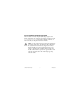
Connecting the NI 9235/9236 The NI 9235/9236 has a 24-terminal detachable spring-terminal connector that provides connections for 8 analog input channels. EXC0 AI0 RC0 EXC2 AI2 RC2 EXC4 AI4 RC4 EXC6 AI6 RC6 1 13 2 14 3 15 4 16 5 17 6 18 7 19 8 20 9 21 10 22 11 23 12 24 EXC1 AI1 RC1 EXC3 AI3 RC3 EXC5 AI5 RC5 EXC7 AI7 RC7 Figure 1. NI 9235/9236 Terminal Assignments NI 9235/9236 6 ni.
You can connect a quarter-bridge sensor to each channel. Each channel has an EXC terminal that provides the excitation voltage stimulus, an AI terminal that measures the bridge voltage, and an RC terminal that provides the quarter-bridge completion. Refer to Figure 2 for an illustration of how to connect quarter-bridge sensors to the NI 9235/9236. EXC* AI** RC* NI 9235/9236 * For best system accuracy, set up the connections to EXC and RC with equal lengths of an identical wire type and gauge.
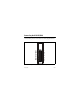
Connecting Wires to the NI 9235/9236 Connector Use a flathead screwdriver with a blade smaller than 2.3 × 1.0 mm (0.09 × 0.04 in.) to connect wires to the detachable spring-terminal connector. Insert the screwdriver into a spring clamp activation slot and press a wire into the corresponding connector terminal, then remove the screwdriver to clamp the wire into the terminal. Refer to the Specifications section for more information about spring-terminal wiring. Figure 3.
Wiring for High-Vibration Applications If an application is subject to high vibration, National Instruments recommends that you use the NI 9965 backshell kit to protect the connections. Refer to Figure 4 for an illustration of the NI 9965 connector backshell. Figure 4. NI 9965 Connector Backshell © National Instruments Corp.
NI 9235/9236 Circuitry The NI 9235/9236 is isolated from earth ground. However, the individual channels are not isolated from each other. The EXC terminals all connect internally to a common excitation supply. You must connect each EXC terminal to only one gage to maintain the channel-to-channel crosstalk performance of the module. Each channel on the NI 9235/9236 has an independent 24-bit ADC and input amplifier that enables you to sample signals from all eight channels simultaneously.
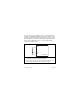
EXC AI + – Filtered Differential Amplifier RC 120 Ω ADC + – 2.0 V Bridge Excitation 50 kΩ Bridge Completion Resistor Shunt Resistor NI 9235 Figure 5. Input Circuitry for One Channel of the NI 9235 © National Instruments Corp.
EXC AI + – Filtered Differential Amplifier RC 350 Ω ADC + – 3.3 V Bridge Excitation 100 kΩ Bridge Completion Resistor Shunt Resistor NI 9236 Figure 6. Input Circuitry for One Channel of the NI 9236 The NI 9235/9236 also includes filters to prevent aliasing. The filters on the NI 9235/9236 filter according to the sampling rate. Refer to the Understanding NI 9235/9236 Filtering section for more information about filtering. NI 9235/9236 12 ni.
Quarter-bridge measurements are inherently sensitive to accuracy degradation due to the lead resistance of wiring from the sensor to the measurement device. For a given change in the gage resistance, the total effective resistance changes slightly less. Accordingly, the measured mV/V reading is less than its true value. However, you can use shunt calibration to quantify the lead wire desensitization, and can then design the software application to correct subsequent readings for this gain error.
Shunt calibration simulates strain input by changing the resistance of an arm in the bridge by a known amount. By shunting, or connecting, a large resistor across one arm of the bridge, a specific change occurs in the bridge voltage ratio. With the connected sensor in a stable, typically unloaded, state, you can measure the output of the bridge before and after the shunt calibration.
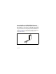
Understanding NI 9235/9236 Filtering The NI 9235/9236 uses a combination of analog and digital filtering to provide an accurate representation of in-band signals while rejecting out-of-band signals. The filters discriminate between signals based on the frequency range, or bandwidth, of the signal. The three important bandwidths to consider are the passband, the stopband, and the alias-free bandwidth.
0.025 Gain (dB) 0.000 –0.025 –0.050 0 1 2 3 4 5 Frequency (kHz) Figure 7. Typical Passband Response for the NI 9235/9236 NI 9235/9236 16 ni.
Stopband The filter significantly attenuates all signals above the stopband frequency. The primary goal of the filter is to prevent aliasing. Therefore, the stopband frequency scales precisely with the data rate. The stopband rejection is the minimum amount of attenuation applied by the filter to all signals with frequencies within the stopband. Alias-Free Bandwidth Any signal that appears in the alias-free bandwidth of the NI 9235/9236 is not an aliased artifact of signals at a higher frequency.
the modules must share a single master timebase source. Refer to the software help for information about configuring the master timebase source for the NI 9235/9236. Visit ni.com/info and enter cseriesdoc for information about C Series documentation. The following equation provides the available data rates of the NI 9235/9236: f M ÷ 256 fs = -------------------n where n is any integer in the set {2; 4, 5, ..., 63}. However, the data rate must remain within the appropriate data rate range.
Sleep Mode This module supports a low-power sleep mode. Support for sleep mode at the system level depends on the chassis that the module is plugged into. Refer to the chassis manual for information about support for sleep mode. If the chassis supports sleep mode, refer to the software help for information about enabling sleep mode. Visit ni.com/info and enter cseriesdoc for information about C Series documentation. Typically, when a system is in sleep mode, you cannot communicate with the modules.
Specifications The following specifications are typical for the range –40 to 70 °C unless otherwise noted. The specifications are the same for the NI 9235 and the NI 9236 unless otherwise noted. Input Characteristics Number of channels.......................... 8 analog input channels Quarter-bridge completion NI 9235....................................... 120 Ω, 10 ppm/°C max NI 9236....................................... 350 Ω, 10 ppm/°C max ADC resolution.................................
Data rate range (fs) using internal master timebase Minimum.................................... 794 S/s Maximum ................................... 10 kS/s Data rate range (fs) using external master timebase Minimum.................................... 195.3125 S/s Maximum ................................... 10.547 kS/s f M ÷ 256 Data rates1 (fs) ..................................... --------------------- , n = {2; 4, 5, ..., 63} n Full-scale range................................. ±29.
Accuracy, NI 9235 Percent of Range†, ‡ (Offset Error) Measurement Conditions Percent of 30 days Reading* after cal. (Gain Error) (±5 °C) 1 year after cal. (±5 °C) Calibrated typ (25 °C, ±5 °C) 0.02% 0.1% 0.15% Calibrated max (–40 to 70 °C) 0.07% 0.17% Uncalibrated typ (25 °C, ±5 °C) 0.15% 1.25% Uncalibrated max (–40 to 70 °C) 0.53% 2.14% 0.4% * Exclusive of lead wire desensitization error. Range equals 29.4 mV/V.
Accuracy, NI 9236 Percent of Range†, ‡ (Offset Error) Measurement Conditions Percent of 30 days Reading* after cal. (Gain Error) (±5 °C) 1 year after cal. (±5 °C) Calibrated typ (25 °C, ±5 °C) 0.02% 0.08% 0.14% Calibrated max (–40 to 70 °C) 0.07% 0.16% 0.39% Uncalibrated typ (25 °C, ±5 °C) 0.15% 0.79% Uncalibrated max (–40 to 70 °C) 0.53% 1.67% * Exclusive of lead wire desensitization error. Range equals 29.4 mV/V.
Channel-to-channel matching (calibrated) Input Signal Frequency (fin) Gain Phase Typical Maximum Maximum 0 to 1 kHz 0.08% 0.11% 0.34°/kHz · fin 0 to 4 kHz 0.17% 0.32% Phase nonlinearity fin = 0 to 1 kHz............................ ±0.002° fin = 0 to 4 kHz............................ ±0.1° Input delay ........................................ 38.2/fs + 11 μs Passband Frequency ................................... 0.45 · fs Flatness (fs = 10 kS/s)................. 33 mdB max Stopband Frequency ....
Alias-free bandwidth ........................ 0.45 · fs Oversample rate ................................ 64 · fs Rejection at oversample rate1 (fs = 10 kS/s) ..................................... 80 dB @ 640 kHz Input noise fs = 1 kS/s NI 9235 ................................ 0.38 μV/Vrms NI 9236 ................................ 0.25 μV/Vrms fs = 10 kS/s NI 9235 ................................ 0.85 μV/Vrms NI 9236 ................................ 0.5 μV/Vrms SFDR (1 kHz, –60 dBFS) NI 9235..................
Crosstalk (fin = 1 kHz) ...................... –100 dB Common-mode voltage, all signals to earth ground................. ±60 VDC CMRR (fin = 0 to 60 Hz) NI 9235....................................... 120 dB NI 9236....................................... 110 dB MTBF ............................................... 566,796 hours at 25 °C; Bellcore Issue 2, Method 1, Case 3, Limited Part Stress Method Note Contact NI for Bellcore MTBF specifications at other temperatures or for MIL-HDBK-217F specifications.
Shunt Calibration Characteristics Shunt calibration accuracy Measurement Conditions NI 9235 NI 9236 Percent of Reading Percent of Reading (Gain Error) (Gain Error) Typical (25 °C, ±5 °C) 0.09% 0.07% Maximum (–40 to 70 °C) 0.22% 0.2% Resistance NI 9235....................................... 50 kΩ NI 9236....................................... 100 kΩ Output value NI 9235....................................... –599.28 μV/V NI 9236....................................... –873.47 μV/V Temperature drift ..
Excitation Characteristics Excitation type .................................. Constant voltage Excitation value NI 9235....................................... 2.0 V ± 1% NI 9236....................................... 3.3 V ± 1% Maximum output current NI 9235....................................... 80 mA NI 9236....................................... 46 mA Power Requirements Power consumption from chassis NI 9235 Active mode ......................... 735 mW max Sleep mode...........................
Thermal dissipation (at 70 °C) NI 9235 Active mode ......................... 735 mW max Sleep mode........................... 25 μW max NI 9236 Active mode ......................... 675 mW max Sleep mode........................... 25 μW max Physical Characteristics If you need to clean the module, wipe it with a dry towel. Spring-terminal wiring...................... 18 to 28 AWG copper conductor wire with 7 mm (0.28 in.) of insulation stripped from the end Weight...........................................
Isolation Channel-to-channel .................... None Channel-to-earth ground Continuous ........................... 60 VDC, Measurement Category I Withstand ............................. 1,000 Vrms, verified by a 5 s dielectric withstand test Measurement Category I is for measurements performed on circuits not directly connected to the electrical distribution system referred to as MAINS voltage. MAINS is a hazardous live electrical supply system that powers equipment.
Safety Standards This product is designed to meet the requirements of the following standards of safety for electrical equipment for measurement, control, and laboratory use: • IEC 61010-1, EN 61010-1 • UL 61010-1, CSA 61010-1 Note For UL and other safety certifications, refer to the product label or visit ni.com/certification, search by module number or product line, and click the appropriate link in the Certification column. Hazardous Locations U.S. (UL) ..........................................
Environmental National Instruments C Series modules are intended for indoor use only but may be used outdoors if installed in a suitable enclosure. Refer to the manual for the chassis you are using for more information about meeting these specifications. Operating temperature (IEC 60068-2-1, IEC 60068-2-2) ..... –40 to 70 °C Storage temperature (IEC 60068-2-1, IEC 60068-2-2) ..... –40 to 85 °C Ingress protection.............................. IP 40 Operating humidity (IEC 60068-2-56).........................
Shock and Vibration To meet these specifications, you must panel mount the system and use the NI 9965 backshell to protect the connections. Operating vibration Random (IEC 60068-2-64)......... 5 grms, 10 to 500 Hz Sinusoidal (IEC 60068-2-6) ....... 5 g, 10 to 500 Hz Operating shock (IEC 60068-2-27)..............................
Note For EMC compliance, operate this device with shielded cabling. CE Compliance This product meets the essential requirements of applicable European directives, as amended for CE markings, as follows: • 2006/95/EC; Low-Voltage Directive (safety) • 2004/108/EC; Electromagnetic Compatibility Directive (EMC) Note Refer to the Declaration of Conformity (DoC) for this product for any additional regulatory compliance information. To obtain the DoC for this product, visit ni.
For additional environmental information, refer to the NI and the Environment Web page at ni.com/environment. This page contains the environmental regulations and directives with which NI complies, as well as other environmental information not included in this document. Waste Electrical and Electronic Equipment (WEEE) EU Customers At the end of their life cycle, all products must be sent to a WEEE recycling center.
Calibration You can obtain the calibration certificate and information about calibration services for the NI 9235/9236 at ni.com/ calibration. Calibration interval ........................... 1 year Where to Go for Support The National Instruments Web site is your complete resource for technical support. At ni.com/support you have access to everything from troubleshooting and application development self-help resources to email and phone assistance from NI Application Engineers.
and follow the calling instructions or dial 512 795 8248.
National Instruments, NI, ni.com, and LabVIEW are trademarks of National Instruments Corporation. Refer to the Terms of Use section on ni.com/legal for more information about National Instruments trademarks. Other product and company names mentioned herein are trademarks or trade names of their respective companies. For patents covering National Instruments products, refer to the appropriate location: Help»Patents in your software, the patents.txt file on your media, or ni.com/patents.