OPERATING INSTRUCTIONS AND SPECIFICATIONS NI 9475 8-Channel, 60 V, High-Speed, Sourcing Digital Output Module Français Deutsch ni.
This document describes how to use the National Instruments 9475 and includes specifications and pin assignments for the NI 9475. Visit ni.com/info and enter rdsoftwareversion to determine which software you need for the modules you are using. For information about installing, configuring, and programming the system, refer to the system documentation. Visit ni.com/info and enter cseriesdoc for information about C Series documentation.
Safety Guidelines Operate the NI 9475 only as described in these operating instructions. This icon denotes that the component may be hot. Touching this component may result in bodily injury. Hot Surface Safety Guidelines for Hazardous Locations The NI 9475 is suitable for use in Class I, Division 2, Groups A, B, C, D, T4 hazardous locations; Class I, Zone 2, AEx nA IIC T4, and Ex nA IIC T4 hazardous locations; and nonhazardous locations only.
Substitution of components may impair suitability for Class I, Division 2. Caution For Zone 2 applications, install the system in an enclosure rated to at least IP 54 as defined by IEC 60529 and EN 60529. Caution For Zone 2 applications, install a protection device between the input signal and the NI 9475 input pin. The device must prevent the input Vsup-to-COM voltage from exceeding 84 V if there is a transient overvoltage condition.
Special Conditions for Marine Applications Some modules are Lloyd’s Register (LR) Type Approved for marine applications. To verify Lloyd’s Register certification, visit ni.com/certification and search for the LR certificate, or look for the Lloyd’s Register mark on the module. To meet radio frequency emission requirements for marine applications, use shielded cables and install the system in a metal enclosure.
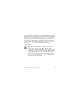
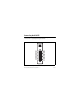
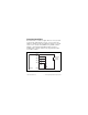
Connecting the NI 9475 The NI 9475 has a 25-pin DSUB connector that provides connections for eight digital output channels. 0 3 4 7 DO0 Vsup DO1 DO2 Vsup DO3 DO4 Vsup DO5 DO6 Vsup DO7 14 15 16 17 18 19 20 21 22 23 24 25 1 2 3 4 5 6 7 8 9 10 11 12 13 COM Vsup COM COM Vsup COM COM Vsup COM COM Vsup COM COM Figure 1. NI 9475 Pin Assignments NI 9475 Operating Instructions and Specifications 6 ni.
Each channel of the NI 9475 has a DO pin to which you can connect a device. Each channel also has a COM pin and a Vsup pin. National Instruments recommends you provide independent COM and Vsup wiring for each channel to minimize current flow in the COM and Vsup wiring. The COM pins are all connected together internally. Each channel has an LED that indicates the state of the channel. When a channel LED is lit, the channel is on. When the LED is dark, the channel is off.
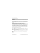
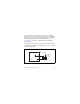
You can directly connect the NI 9475 to a variety of industrial devices such as solenoids, motors, actuators, relays, and lamps. Make sure the devices you connect to the NI 9475 are compatible with the output specifications of the module. Refer to the Specifications section for more information about the output specifications. Connect the device to DO and connect the common of the device to COM. Refer to Figure 2 for an illustration of how to connect a device to the NI 9475.
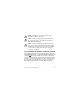
Increasing Current Drive Each channel has a continuous output current of 1 A. If you want to increase the output current to a device, you can connect any number of channels together in parallel. For example, if you want to drive 4 A of current, connect DO<0..3> in parallel as shown in Figure 3. You must turn all parallel channels on and off simultaneously so that the current on any single channel cannot exceed the 1 A rating.
I/O Protection The NI 9475 is short-circuit proof in accordance with IEC 1131-2 and provides overcurrent protection. Understanding Short-Circuit-Proof Devices Each channel on the NI 9475 has circuitry that protects it from current surges resulting from short circuits.
Higher inrush currents that exist for less than the trip time do not trip the protection circuitry. Refer to the Specifications section for more information about the maximum continuous output current, short-circuit behavior, and short-circuit trip time. You also can refer to the IEC 1131-2 standard for more information about short-circuit-proof devices. Because the NI 9475 includes internal flyback diodes, you do not need to add external diodes when connecting to switching energy storing devices.
overcurrent condition occurs. A channel LED may be on even if the channel is off because of an overcurrent condition. To determine if the channel is in an overcurrent state, measure the voltage between DO and Vsup. If the voltage is equal to the voltage of the external power supply connected to the module, the channel is in an overcurrent state. Resetting Channels After an Overcurrent Condition After you have determined and fixed the cause of the overcurrent condition, reset the channel by turning it off.
support for sleep mode. Refer to the software help for information about enabling sleep mode. Visit ni.com/info and enter cseriesdoc for information about C Series documentation. Typically, when a system is in sleep mode, you cannot communicate with the modules. In sleep mode, the system consumes minimal power and may dissipate less heat than it does in normal mode. Refer to the Specifications section for more information about power consumption and thermal dissipation.
Output impedance (R0) ..................... 0.14 Ω max Continuous output current (I0), per channel........................................ 1 A max Output voltage .................................. Vsup – (I0 · R0) I/O protection Voltage........................................ 60 VDC max Reversed voltage ........................
MTBF ............................................... 1,096,296 hours at 25 °C; Bellcore Issue 6, Method 1, Case 3, Limited Part Stress Method Note Contact NI for Bellcore MTBF specifications at other temperatures or for MIL-HDBK-217F specifications. Power Requirements Power consumption from chassis Active mode ............................... 355 mW max Sleep mode ................................. 25 μW max Thermal dissipation (at 70 °C) Active mode ............................... 1.5 W max Sleep mode .....
Safety Maximum Voltage1 Connect only voltages that are within the following limits. Vsup-to-COM..................................... 60 VDC, Measurement Category I Measurement Category I is for measurements performed on circuits not directly connected to the electrical distribution system referred to as MAINS voltage. MAINS is a hazardous live electrical supply system that powers equipment. This category is for measurements of voltages from specially protected secondary circuits.
Isolation Voltages Channel-to-channel........................... No isolation between channels Channel-to-earth ground Continuous ................................. 60 VDC, Measurement Category I Withstand....................................
Hazardous Locations U.S. (UL) .......................................... Class I, Division 2, Groups A, B, C, D, T4; Class I, Zone 2, AEx nA IIC T4 Canada (C-UL) ................................. Class I, Division 2, Groups A, B, C, D, T4; Class I, Zone 2, Ex nA IIC T4 Europe (DEMKO)............................. Ex nA IIC T4 Environmental National Instruments C Series modules are intended for indoor use only but may be used outdoors if installed in a suitable enclosure.
Operating humidity (IEC 60068-2-56).............................. 10 to 90% RH, noncondensing Storage humidity (IEC 60068-2-56).............................. 5 to 95% RH, noncondensing Maximum altitude............................. 2,000 m Pollution Degree (IEC 60664) .......... 2 Shock and Vibration To meet these specifications, you must panel mount the system. Operating vibration Random (IEC 60068-2-64)......... 5 grms, 10 to 500 Hz Sinusoidal (IEC 60068-2-6) .......
Electromagnetic Compatibility This product is designed to meet the requirements of the following standards of EMC for electrical equipment for measurement, control, and laboratory use: • EN 61326 EMC requirements; Industrial Immunity • EN 55011 Emissions; Group 1, Class A • CE, C-Tick, ICES, and FCC Part 15 Emissions; Class A Note For EMC compliance, operate this device with shielded cabling.
Note Refer to the Declaration of Conformity (DoC) for this product for any additional regulatory compliance information. To obtain the DoC for this product, visit ni.com/certification, search by module number or product line, and click the appropriate link in the Certification column. Environmental Management National Instruments is committed to designing and manufacturing products in an environmentally responsible manner.
Waste Electrical and Electronic Equipment (WEEE) EU Customers At the end of their life cycle, all products must be sent to a WEEE recycling center. For more information about WEEE recycling centers and National Instruments WEEE initiatives, visit ni.com/ environment/weee.htm. ⬉ᄤֵᙃѻક∵ᶧࠊㅵ⧚ࡲ⊩ ˄Ё RoHS˅ Ёᅶ᠋ National Instruments ヺড়Ё⬉ᄤֵᙃ ѻકЁ䰤ࠊՓ⫼ᶤѯ᳝ᆇ⠽䋼ᣛҸ (RoHS)DŽ݇Ѣ National Instruments Ё RoHS ড়㾘ᗻֵᙃˈ䇋ⱏᔩ ni.com/environment/rohs_chinaDŽ (For information about China RoHS compliance, go to ni.
Where to Go for Support The National Instruments Web site is your complete resource for technical support. At ni.com/support you have access to everything from troubleshooting and application development self-help resources to email and phone assistance from NI Application Engineers. National Instruments corporate headquarters is located at 11500 North Mopac Expressway, Austin, Texas, 78759-3504. National Instruments also has offices located around the world to help address your support needs.
Korea 82 02 3451 3400, Lebanon 961 (0) 1 33 28 28, Malaysia 1800 887710, Mexico 01 800 010 0793, Netherlands 31 (0) 348 433 466, New Zealand 0800 553 322, Norway 47 (0) 66 90 76 60, Poland 48 22 3390150, Portugal 351 210 311 210, Russia 7 495 783 6851, Singapore 1800 226 5886, Slovenia 386 3 425 42 00, South Africa 27 0 11 805 8197, Spain 34 91 640 0085, Sweden 46 (0) 8 587 895 00, Switzerland 41 56 2005151, Taiwan 886 02 2377 2222, Thailand 662 278 6777, Turkey 90 212 279 3031, United Kingdom 44 (0) 1635 5