CAN Getting Started with Your PXI-8461 or PXI-8460 and the NI-CAN™ Software for Windows NT PXI-8461 or PXI-8460 and NI-CAN for Windows NT September 1999 Edition Part Number 322006B-01
Worldwide Technical Support and Product Information www.natinst.
Important Information Warranty The PXI hardware is warranted against defects in materials and workmanship for a period of one year from the date of shipment, as evidenced by receipts or other documentation. National Instruments will, at its option, repair or replace equipment that proves to be defective during the warranty period. This warranty includes parts and labor.
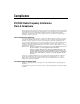
Compliance FCC/DOC Radio Frequency Interference Class A Compliance This equipment generates and uses radio frequency energy and, if not installed and used in strict accordance with the instructions in this manual, may cause interference to radio and television reception. Classification requirements are the same for the Federal Communications Commission (FCC) and the Canadian Department of Communications (DOC).
Contents About This Manual How To Use the Manual Set..........................................................................................ix Conventions ...................................................................................................................x Related Documentation..................................................................................................xi Chapter 1 Introduction What You Need to Get Started ...............................................................
Contents Appendix B Cabling Requirements for PXI-8461 High-Speed CAN Connector Pinouts ......................................................................................................... B-1 Power Supply Information for the High-Speed CAN Ports .......................................... B-2 Bus Power Supply Requirements .................................................................................. B-4 Cable Specifications ...........................................................................
Contents Glossary Figures Figure 2-1. Figure 2-2. Figure 2-3. Figure 2-4. Add/Remove Programs Properties Dialog Box.....................................2-2 Installing the PXI Hardware..................................................................2-4 PXI-8461 That Is Working Properly .....................................................2-5 NI-CAN Hardware Settings Dialog Box...............................................2-6 Figure 3-1. NI-CAN Diagnostic Utility after Testing...........................
About This Manual This manual contains instructions to help you install and configure your PXI-8461 (one port and two port) or PXI-8460 (one port or two port) and the NI-CAN software for Windows NT. This manual uses PXI-8461 or PXI-8460 to refer to both the one port and two port versions of the boards. This manual assumes that you are already familiar with Windows NT.
About This Manual Use the NI-CAN Programmer Reference Manual for specific information about each NI-CAN function and object, including format, parameters, and possible errors. Conventions The following conventions appear in this manual: » The » symbol leads you through nested menu items and dialog box options to a final action. The sequence File»Page Setup»Options directs you to pull down the File menu, select the Page Setup item, and select Options from the last dialog box.
About This Manual Related Documentation The following documents contain information that you may find helpful as you read this manual: • ANSI/ISO Standard 11898-1993, Road Vehicles—Interchange of Digital Information—Controller Area Network (CAN) for High-Speed Communication • ANSI/ISO Standard 11519-2-1994, Road Vehicles—Low-Speed Serial Data Communication—Part 2: Low-Speed Controller Area Network (CAN) • CAN Specification Version 2.0, 1991, Robert Bosch Gmbh.
1 Introduction This chapter lists what you need to get started, provides an overview of the PXI hardware and the NI-CAN software for Windows NT, and describes optional equipment you can order. What You Need to Get Started Make sure you have all of the following items before you attempt to install the hardware and software: ❑ Windows NT 3.51 or later installed on your computer – PXI-8461 one port – PXI-8461 two port – PXI-8460 one port – PXI-8460 two port ❑ 3.5 in., high-density (1.
Chapter 1 Introduction specification for CAN and is also optically isolated to 500 V. CAN interfacing is accomplished using the Intel 82527 CAN controller chip. The PXI-8461 supports a wide variety of transfer rates up to 1 Mb/s. The PXI-8460 supports rates up to 125 kb/s. The CAN physical layer on the PXI-8461 and PXI-8460 can be powered either internally (from the board) or externally (from the bus cable power). The power source for the CAN physical layer for each port is configured with a jumper.
Chapter 1 Introduction • Language interface libraries for Microsoft Visual C/C++ 2.0 or later, LabWindows/CVI 4.0 or later, and LabVIEW 4.0 or later • Example programs that use NI-CAN functions Optional Programming Tools Your kit includes the NI-CAN software for Windows NT. In addition, you can order the LabWindows/CVI, LabVIEW, or BridgeVIEW software from National Instruments.
Installation and Configuration 2 This chapter describes how to install and configure the NI-CAN software for Windows NT and the PXI-8461 or PXI-8460 hardware. Install the NI-CAN Software Install the NI-CAN software for Windows NT before you install your hardware. Installation for Windows NT 3.51 1. Log on as Administrator or as a user with Administrator privileges. The NI-CAN setup program must have Administrator privileges because the program modifies the configuration registry of your system. 2.
Chapter 2 Installation and Configuration 3. Double-click on the Add/Remove Programs icon in the Control Panel to launch the Add/Remove Programs applet. A dialog box similar to the one in Figure 2-1 appears. Figure 2-1. Add/Remove Programs Properties Dialog Box You can use this same applet to uninstall the NI-CAN software at a later time. Refer to Appendix A, Uninstalling the Hardware and Software, for more information. 4. Click on the Install button. 5.
Chapter 2 Installation and Configuration Install the Hardware This section describes how to install your PXI-8461or PXI-8460 hardware. Check the Configuration of Your PXI-8461 or PXI-8460 If you plan to use your CAN board in a system where bus power is available, you may want to configure the power supply jumpers on your board. See Appendix B, Cabling Requirements for PXI-8461 High-Speed CAN, for more information.
Chapter 2 Installation and Configuration 5. Insert the PXI board into the selected 5 V slot. Use the injector/ejector handle to fully inject the device into place. Figure 2-2 shows how to install the PXI board into a PXI or CompactPCI chassis. 3 ON STA ND BY 1 2 3 4 5 6 7 8 2 4 1 1 2 Injector/Ejector Handle (In Down Position) PXI Board 3 4 PXI Chassis Injector/Ejector Rail Figure 2-2. Installing the PXI Hardware 6.
Chapter 2 Installation and Configuration Configure the NI-CAN Software The NI-CAN Configuration utility is located in the Windows NT Control Panel. You can use it to examine or modify the configuration of the NI-CAN software. The context-sensitive online help, available by right-clicking on any of the controls on the configuration utility buttons, includes all the information you need to configure the NI-CAN software.
Chapter 2 Installation and Configuration To view information about the NI-CAN software configuration for the PXI-8461 or PXI-8460, click on the Settings button. Figure 2-4 shows the Settings dialog box. Figure 2-4. NI-CAN Hardware Settings Dialog Box Each port of the PXI-8461 or PXI-8460 is configured from this tab. Use the drop-down box nearest the top of the tab to select the physical port number to configure.
3 Verify the Installation This chapter describes how to verify the hardware and software installation. You can use the NI-CAN Diagnostic utility, installed with your NI-CAN software, to test the hardware and software installation. The utility verifies that your hardware and software are functioning properly and that the configuration of your hardware does not conflict with anything else in your system. To run the utility, select the NI-CAN Diagnostic item: • Windows NT 3.
Chapter 3 Verify the Installation You can get details about any tested CAN interface by selecting the interface and clicking on the Details button. For each failed CAN interface, select it and click on the Details button to get a description of the failure. Use that information and the information in Appendix D, Troubleshooting and Common Questions, to troubleshoot the problem.
4 Begin to Use the NI-CAN Software This chapter helps you get started with the NI-CAN software for Windows NT. Using the NI-CAN Software The functions provided by the NI-CAN software are similar to those provided by many other device drivers. For example, NI-CAN has open, close, read, and write functions. NI-CAN provides two different levels of access to a CAN network: the CAN Network Interface Object and CAN Objects.
Chapter 4 Begin to Use the NI-CAN Software General Programming Considerations As you begin developing your Win32 NI-CAN application, remember the following points: • For your LabVIEW or BridgeVIEW application, you must use the NI-CAN LabVIEW functions in nican.llb. • For your C/C++ application, you must include the NI-CAN header file, nican.h, in your source code. • The NI-CAN software is accessed through the 32-bit DLL, nican.
Uninstalling the Hardware and Software A This appendix describes how to uninstall the PXI-8461 or PXI-8460 hardware and the NI-CAN software from Windows NT. Uninstalling the Hardware from Windows NT Because Windows NT 3.51 and 4.0 do not maintain hardware information for the board, you just need to physically remove your PXI hardware from your computer. To do so, shut down Windows NT, power off your PXI or CompactPCI chassis, remove any cables attached to your board, and physically remove the board.
Appendix A Uninstalling the Hardware and Software Complete the following steps to remove the NI-CAN software from Windows NT 4.0: 1. Select the Add/Remove Programs icon under Start»Settings» Control Panel. A dialog box similar to the one in Figure A-1 appears. This dialog box lists the software available for removal. Figure A-1. Add/Remove Programs Properties Dialog Box 2. Select the NI-CAN software you want to remove and click on the Add/Remove button.
B Cabling Requirements for PXI-8461 High-Speed CAN This appendix describes the cabling requirements for the hardware. Cables should be constructed to meet these requirements and the requirements of the other CAN or DeviceNet devices in the network. Connector Pinouts Depending on the type of PXI board you are installing, it either has DB-9 D-Sub connector(s) or Combicon-style pluggable screw terminal connector(s). The 9-pin D-Sub follows the pinout recommended by CiA Draft Standard 102.
Appendix B Cabling Requirements for PXI-8461 High-Speed CAN V– CAN_L Shield CAN_H V+ The 5-pin Combicon-style pluggable screw terminal follows the pinout required by the DeviceNet Specification. Figure B-2 shows the pinout for this connector. 1 2 3 4 5 Figure B-2. Pinout for 5-Pin Combicon-Style Pluggable Screw Terminal CAN_H and CAN_L are signal lines that carry the data on the CAN network. These signals should be connected using twisted-pair cable.
Appendix B Cabling Requirements for PXI-8461 High-Speed CAN 3 4 2 1 5 1 2 Power Supply Jumper J6 Power Supply Jumper J5 3 4 Assembly Number Product Name 5 Serial Number Figure B-3. PXI-8461 Part Locator Diagram Connecting pins 1 and 2 of a jumper configures the CAN physical layer to be powered externally (from the bus cable power). In this configuration, the power must be supplied on the V+ and V– pins on the port connector.
Appendix B Cabling Requirements for PXI-8461 High-Speed CAN Figure B-4 shows how to configure your jumpers for internal or external power supplies. INT 3 2 EXT 1 a. Internal Power Mode INT 3 2 EXT 1 b. External Power Mode Figure B-4. Power Source Jumpers The CAN physical layer is still isolated regardless of the power source chosen.
Appendix B Cabling Requirements for PXI-8461 High-Speed CAN Cable Specifications Cables should meet the physical medium requirements specified in ISO 11898, shown in Table B-2. Belden cable (3084A) meets all of those requirements and should be suitable for most applications. Table B-2.
Appendix B Cabling Requirements for PXI-8461 High-Speed CAN Number of Devices The maximum number of devices that you can connect to a CAN port depends on the electrical characteristics of the devices on the network. If all of the devices meet the requirements of ISO 11898, at least 30 devices may be connected to the bus. Higher numbers of devices may be connected if the electrical characteristics of the devices do not degrade signal quality below ISO 11898 signal level specifications.
Appendix B Cabling Requirements for PXI-8461 High-Speed CAN Cabling Example Figure B-6 shows an example of a cable to connect two CAN devices. For the internal power configuration, no V+ connection is required. 5-Pin Combicon 9-Pin D-Sub Pin 4 Pin 7 Pin 2 Pin 2 Pin 3 Pin 5 Pin 5 Pin 9 Pin 1 Pin 3 CAN_H 120Ω 9-Pin D-Sub 5-Pin Combicon Pin 7 Pin 4 Pin 2 Pin 2 Pin 5 Pin 3 Pin 9 Pin 5 Pin 3 Pin 1 120Ω CAN_L Shield V+ V– Power Connector V+ V– Figure B-6.
C Cabling Requirements for PXI-8460 Low-Speed CAN This appendix describes the cabling requirements for the PXI-8460 hardware. Cables should be constructed to meet these requirements, as well as the requirements of the other CAN devices in the network. Connector Pinouts The PXI-8460 has DB-9 D-Sub connector(s). The 9-pin D-Sub follows the pinout recommended by CiA DS 102. Figure C-1 shows the pinout for this connector.
Appendix C Cabling Requirements for PXI-8460 Low-Speed CAN CAN_H and CAN_L are signal lines that carry the data on the CAN network. These signals should be connected using twisted-pair cable. The V+ and V– pins are used to supply bus power to the CAN physical layer if external power is required for the CAN physical layer. If internal power for the CAN physical layer is used, the V- pin serves as the reference ground for CAN_H and CAN_L.
Appendix C Cabling Requirements for PXI-8460 Low-Speed CAN Connecting pins 2 and 3 of a jumper configures the CAN physical layer to be powered internally (from the card). In this configuration, the V– signal serves as the reference ground for the isolated signals. Even if the CAN physical layer is powered internally, the fault-tolerant CAN transceiver still requires bus power to be supplied in order for it to monitor the power supply (battery) voltage.
Appendix C Cabling Requirements for PXI-8460 Low-Speed CAN Cable Specifications Cables should meet the physical medium requirements specified in ISO 11519-2, shown in Table C-2. Belden cable (3084A) meets all of those requirements, and should be suitable for most applications. Table C-2.
Appendix C Cabling Requirements for PXI-8460 Low-Speed CAN Low-Speed Termination Every device on the low-speed CAN network requires a termination resistor for each CAN data line: RRTH for CAN_H and RRTL for CAN_L. Figure C-4 shows termination resistor placement in a low-speed CAN network. Low-speed CAN Device RTL CAN_L Low-speed CAN Device RTH CAN_H RTL CAN_L Low-speed CAN Device RTH CAN_H RTL CAN_L RTH CAN_H CAN_H CAN_L Figure C-4.
Appendix C Cabling Requirements for PXI-8460 Low-Speed CAN Philips also recommends an individual device RTH and RTL termination of 500 Ω to 16 kΩ. The PXI-8460 board ships with mounted RTH and RTL values of 510 Ω ±5% per port. The PXI-8460 kit also includes a pair of 15 kΩ ±5% resistors for each port.
Appendix C Cabling Requirements for PXI-8460 Low-Speed CAN Replacing the Termination Resistors Follow these steps to replace the termination resistors, after you have determined the correct value in the previous section, Determining the Necessary Termination Resistance for Your Board. 1. Remove the termination resistors on your PXI-8460. Figure C-5 shows the location of the termination resistor sockets on a PXI-8460. 1 2 1 Port 1 Termination Resistors 2 Port 2 Termination Resistors Figure C-5.
Appendix C Cabling Requirements for PXI-8460 Low-Speed CAN 3. Insert the replacement resistors into the empty sockets. 4. Refer to Install the Hardware, in Chapter 2, Installation and Configuration, to complete the hardware installation. Cabling Example Figure C-7 shows an example of a cable to connect two low-speed CAN devices. For the internal power configuration, the V+ connection is required for the low-speed transceiver to operate as specified in the Philips data sheet.
Troubleshooting and Common Questions D This appendix describes how to troubleshoot problems and answers some common questions. Missing Board in the NI-CAN Configuration Utility The NI-CAN Configuration utility contains configuration information for all of the CAN hardware it is aware of that is installed in your system. To start the NI-CAN Configuration utility, double-click on the NI-CAN Configuration icon in the Control Panel: • Windows NT 3.
Appendix D Troubleshooting and Common Questions NI-CAN Software Problem Encountered This error occurs if the NI-CAN Diagnostic utility detects that it is unable to communicate correctly with the hardware using the installed NI-CAN software. If you get this error, shut down your computer, restart it, and run the NI-CAN Diagnostic utility again. If the problem persists, try reinstalling the NI-CAN software for Windows NT.
Appendix D Troubleshooting and Common Questions How do I connect a CAN cable to my CAN port? You will need to use an appropriate cable. For information about cabling requirements for National Instruments CAN hardware, refer to Appendix B, Cabling Requirements for PXI-8461 High-Speed CAN or Appendix C, Cabling Requirements for PXI-8460 Low-Speed CAN. Are interrupts required for the PXI-8461 and PXI-8460? Yes, one interrupt per board is required.
E Specifications This appendix describes the physical characteristics of the hardware and the recommended operating conditions. PXI-8461 One Port and Two Port Dimensions............................................. PXI 3U Module 100 by 160 mm (3.94 by 6.30 in.) Power requirement ................................. +5 VDC 500 mA typical I/O connector..........................................
Appendix E Specifications Operating environment Component temperature ..................0 to 55 °C Relative humidity ............................10% to 90%, noncondensing Storage environment Temperature.....................................–20 to 70 °C Relative humidity ............................10% to 90%, noncondensing High-Speed CAN Port Characteristics for Bus-Powered Ports Power requirement..................................10–30 V, 40 mA typical 100 mA maximum Isolation ............................
Technical Support Resources F This appendix describes the comprehensive resources available to you in the Technical Support section of the National Instruments Web site and provides technical support telephone numbers for you to use if you have trouble connecting to our Web site or if you do not have internet access. NI Web Support To provide you with immediate answers and solutions 24 hours a day, 365 days a year, National Instruments maintains extensive online technical support resources.
Appendix F Technical Support Resources Software-Related Resources • Instrument Driver Network—A library with hundreds of instrument drivers for control of standalone instruments via GPIB, VXI, or serial interfaces. You also can submit a request for a particular instrument driver if it does not already appear in the library. • Example Programs Database—A database with numerous, non-shipping example programs for National Instruments programming environments.
Glossary Prefix Meaning Value n- nano- 10 –9 m- milli- 10 –3 k- kilo- 10 3 M- mega- 10 6 ° degrees Ω ohms % percent A amperes ANSI American National Standards Institute b bits B bytes C Celsius CAN Controller Area Network CiA CAN in Automation DC direct current DLL dynamic link library FCC Federal Communications Commission ft feet HMI Human Machine Interface Hz hertz IEEE Institute of Electrical and Electronic Engineers in.
Glossary ISO International Standards Organization LED light-emitting diode m meters PC personal computer PCI peripheral component interconnect PCMCIA Personal Computer Memory Card International Association PLC Programmable Logic Controller RAM random-access memory resource hardware settings used by National Instruments CAN hardware, including an interrupt request level (IRQ) and an 8 KB physical memory range (such as D0000 to D1FFF hex) s seconds V volts VDC volts direct current VXI