GETTING STARTED GUIDE NI Digital Waveform Generator/Analyzer This document explains how to install, configure, test, and set up a National Instruments digital waveform generator/analyzer.
5. Installing the Hardware..........................................................................8 Installing a PXI Module.....................................................................8 Installing a PCI Device ......................................................................10 6. Configuring and Testing in MAX..........................................................11 Using the Test Panel to Generate and Acquire Data .........................12 7. Connecting Signals .........................
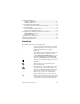
CompactPCI CompactPCI refers to the core specification defined by the PCI Industrial Computer Manufacturers Group (PICMG). italic Italic text denotes variables, emphasis, or a cross reference. This font also denotes text that is a placeholder for a word or value that you must supply. monospace Text in this font denotes text or characters that you should enter from the keyboard, sections of code, programming examples, and syntax examples.
• • • • • • 1/8 in. flathead screwdriver Number 1 Phillips screwdriver Microsoft Internet Explorer 5.5 or later Measurement & Automation Explorer (MAX) 3.1 or later A screen resolution of 800 × 600 with 256 colors (required for the NI Script Editor) The appropriate cable for your device, as shown in the following table: Table 1.
• • Windows 2000/NT/XP, with all available critical updates and service packs One of the following application development environments (ADEs): – LabVIEW 7.0 or later (LabVIEW 7.1 or later is required to use the NI-HSDIO Express VIs) – LabVIEW Real-Time Module 7.1 – LabWindows™/CVI™ 6.0 or later – Microsoft Visual C++ (MSVC) 6.0 or later 2. Unpacking The NI digital waveform generator/analyzer ships in an antistatic package to prevent electrostatic discharge (ESD).
❑ Other documentation included with the digital waveform generator/analyzer and driver software. Refer to the Documentation section for a list of the documentation you may have. Documentation The NI digital waveform generator/analyzer kit may also include the following documents: • NI digital waveform generator/analyzer specifications—This printed document provides specifications for your device.
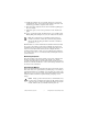
Install NI-HSDIO NI-HSDIO features a set of operations and attributes that allow you to programmatically configure and control the digital waveform generator/analyzer. To install NI-HSDIO, complete the following steps: 1. Insert the first CD of the NI-HSDIO CD set. The NI-HSDIO installer should open automatically. If not, select Start»Run, and enter x:\setup.exe, where x is the letter of the CD drive. 2. Follow the instructions in the installation prompts.
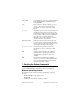
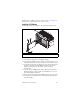
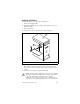
information on re-enabling your device, refer to the I Received a Thermal Shutdown Error section in Appendix B: Troubleshooting. Installing a PXI Module To install the module, refer to Figure 1 and complete the following steps: 1 4 NI PX 3 I-1 04 2 2 1 PXI Chassis 2 Ejector Handle 3 Captive Screw 4 NI PXI Device Figure 1. PXI Installation 1. Power down the chassis before installing the module. 2. If the chassis has multiple fan speed settings, ensure that the fans are set to the highest setting.
7. Holding the module by the ejector handle, slide it into an empty slot, ensuring that the base card (on the left when looking at the front of the module) engages with the card guides in the chassis. 8. Slide the module completely into the chassis and latch by pulling up on the ejector handle. 9. Tighten the captive screws at the top and bottom of the module front panel. 10. Before operating the module, install all chassis covers and filler panels.
Installing a PCI Device To install your PCI device, complete the following steps: 1. Power off and unplug the PC. 2. If the PC has multiple fan speed settings, ensure that the fans are set to the highest setting. 3. Remove the PC cover. 4. Insert the device into an open PCI slot, as shown in Figure 2. 3 2 1 1 NI PCI Device 2 PCI Slot 3 Personal Computer Figure 2.
a different chassis. Improperly secured devices may affect the accuracy of device specifications. 6. Before operating the device, install all filler panels. Missing filler panels disrupt the necessary air circulation in the PC. 7. Replace the PC cover. 8. Plug in and power on the PC. Maintaining PCI Systems Inspect the onboard fan on a regular basis to prevent fan and air circulation path blockage. Cleaning frequency depends on the amount of use and the operating environment. 6.
Figure 3. Configuration Tree Shortcut Menu b. When the self-test finishes, a message window appears to indicate if an error occurred. If an error occurred, refer to ni.com/support for troubleshooting information. Tip If you need to reset the device with a hard reset, you can do so by right-clicking the device and selecting Reset Device from the shortcut menu shown in Figure 3. 6. Record the device name assigned to the digital device. You need this information when you program the device.
6. Enter values for the generation and acquisition voltages in the controls below the Clock Frequency control. You can choose from standard logic families (NI 654X/655X) or enter High and Low values to create your own custom levels (NI 655X). 7. Choose a fill pattern. The following figure shows the pattern control and the first few signals in the window. Tip When generating a Marching Ones or Marching Zeroes waveform, it is convenient to make the waveform size a multiple of the number of selected channels.
7. Connecting Signals This section discusses what connections you can make to the device, and how to connect signals to the device for performing dynamic acquisition and dynamic generation. For device front panel diagrams and connector descriptions, refer to Appendix A: Device Front Panels. Connecting Cables and Accessories To make connections to the NI digital waveform generator/analyzer front panel SMB jack connectors, use a shielded 50 Ω coaxial cable with an SMB plug end.
2 NI PXI-1042 NI PXI-6551 50 MHz Digital I/O ACCESS ACTIVE CLK IN PFI 0 CLK OUT DIGITAL DATA & CONTROL J15 J5 J6 3 1 1 PXI Chassis with NI Digital Waveform Generator/Analyzer 2 SHC68-C68-D2 Cable 3 NI CB-2162 Accessory Figure 4. Connecting the NI CB-2162 Accessory NI PXI-1042 NI PXI-6551 50 MHz Digital I/O ACCESS ACTIVE CLK IN PFI 0 DIGITAL DATA & CONTROL CLK OUT 1 2 3 1 PXI Chassis with NI Digital Waveform Generator/Analyzer 2 NI SMB-2163 Accessory 3 SHC68-C68-D2 Cable Figure 5.
Note If you are creating your own accessory to use with your device, you can purchase the mating connector for the VHDCI cable from NI (part number 778914-01). Whether you use NI cables and accessories or design your own, you should properly terminate cables to avoid improper measurements due to signal reflections, overshoot, and undershoot. Refer to the NI Digital Waveform Generator/Analyzer Help for more information about signal termination.
Dynamic Acquisition When performing dynamic acquisition with the NI 654X/655X, the source generating the signals needs a matched source impedance as close to 50 Ω as possible to minimize signal reflections and maintain optimal signal quality. Figure 7 shows a diagram of a dynamic acquisition system using the NI 655X as an example. RT 50 NI 655X RS Cable Peripheral Device NI CB-2162 Figure 7.
8. Programming the Digital Waveform Generator/Analyzer You can generate or acquire digital data with the NI digital waveform generator/analyzer using NI-HSDIO. You also can run the NI-HSDIO examples to demonstrate the functionality of your device. NI-HSDIO Instrument Driver The NI-HSDIO API features a set of operations and attributes that exercise all the functionality of the device, including configuration, control, and other device-specific functions.
1 2 3 4 5 6 7 8 9 10 11 12 13 14 15 16 17 18 19 20 21 22 23 24 25 26 27 28 29 30 31 32 33 34 35 36 37 38 39 40 41 42 43 44 45 46 47 48 49 50 51 52 53 54 55 56 57 58 59 60 61 62 63 64 65 66 67 68 DIO 30 GND DIO 28 GND DIO 26 GND DIO 24 GND DIO 22 GND DIO 20 GND DIO 18 GND DIO 16 GND DIO 14 RESERVED DIO 12 GND DIO 10 GND DIO 8 GND DIO 6 RESERVED DIO 4 GND DIO 2 PFI 2 DIO 0 GND STROBE GND NI PXI-6541 50 MHz Digital I/O ACCESS NI PCI-6541 CLK IN ACTIVE PFI 0 CLK IN CLK OUT PFI 0 CLK OUT DIGITAL DATA
Table 4. NI 654X DDC Connector Pins Pins Signal Name Signal Type Signal Description 33 DDC CLK OUT Control Output terminal for the exported Sample clock. 67 STROBE Control Terminal for the external Sample clock source which can be used for pattern acquisition. DIO <0..31> Data Bidirectional digital I/O data channels 0 through 31. 26, 30, 64 PFI <1..3> Control Input terminals to the NI 654X for external triggers, or output terminals from the NI 654X for events.
Figure 9 shows the NI 6551 front panels and pinout, which are identical to those of the NI 6552. The DDC signals are described in Table 5. The SMB connectors are described in Table 7. The LEDs are described in Tables 8 and 9.
Table 5. NI 655X DDC Connector Pins Pins Signal Name Signal Type Signal Description 33 DDC CLK OUT Control Output terminal for the exported Sample clock. 67 STROBE Control Terminal for the external Sample clock source which can be used for pattern acquisition. 13, 15, 17, 19, 21, 23, 25, 27, 29, 31, 47, 49, 51, 53, 55, 57, 59, 61, 63, 65 DIO <0..19> Data Bidirectional digital I/O data channels 0 through 19. 26, 30, 64 PFI <1..
3 PFI_2* 6 PFI_3* / GND RESERVED(NC) DIO 0* DIO 1* DIO 2* DIO 3* DIO 4* DIO 5* DIO 6* DIO 7* DIO 8* DIO 9* DIO 10* DIO 11* DIO 12* DIO 13* DIO 14* DIO 15* STROBE* DDC CLK OUT LVDS* RESERVED(NC) DDC CLK OUT LVPECL* 1 4 2 PFI_1 5 PFI_2 7 9 8 10 12 11 13 15 14 16 18 17 19 21 20 22 24 23 25 27 26 28 30 29 31 33 32 34 36 35 37 39 38 40 42 41 43 45 44 46 48 47 49 51 50 52 54 53 55 57 56 58 60 59 61 63 62 64 66 65 67 69 68 70 72 71 73 PFI_3 GND GND GND GND RESERVED(NC) GND DIO 0 GND DIO 1 GND DIO 2 GND
If you are designing a custom cabling solution with connector (779157-01) and cable (192744-01), the NI665X pinout is reversed at the end connector. For example, the signal shown on pin 1 shown in the previous figure would map to pin 73 at the end connector. Note Table 6. NI 656X DDC Connector Pins Pins Signal Name Signal Type Signal Description 65 DDC CLK OUT LVDS Control Positive terminal for the exported Sample clock.
Table 6. NI 656X DDC Connector Pins (Continued) Pins Signal Type Signal Name Signal Description 1, 4, 7, 10, 13, 16, 19, 22, 25, 28, 31, 34, 37, 40, 43, 46, 49, 52, 55, 58 GND Ground Ground reference for signals. 11, 12, 68, 69 RESERVED N/A These terminals are reserved for future use. Do not connect to these pins. Table 7.
Table 9. ACCESS LED Indicators Color Indications Off Device not ready. Amber Device being accessed by software. Green Device ready to be programmed. Red Running the niHSDIO Self Test VI or calling niHSDIO_self_test produced a failure. Appendix B: Troubleshooting Device Front Panel ACCESS LED on PXI Module is Off When PXI Chassis is On If the ACCESS LED is not lit after you power on the PXI chassis, a problem may exist with the PXI power rails, a hardware device, or the LED.
Device Does Not Appear in MAX Complete the following steps if the NI device does not appear in MAX: 1. In the MAX Configuration pane, click Devices and Interfaces to expand the category. 2. Click NI-DAQmx Devices and press to refresh the list of installed devices. 3. If the device is still not listed, power down the system, ensure the device is correctly installed, and restart. 4. If the device still does not appear under NI-DAQmx Devices, contact NI support at ni.com/support.
Performance Issues Using MXI Connection When using a MXI connection to control the PXI chassis, the MXI Optimization Application must be run prior to using the NI device. By default, this application runs automatically when Windows starts. Use of a MXI connection without running this application may result in a time exceeded or internal software error, or an initialization, timeout, or performance issue when using the NI device.
your service request at ni.com/support and follow the calling instructions or dial 512 795 8248.
National Instruments, NI, ni.com, and LabVIEW are trademarks of National Instruments Corporation. Refer to the Terms of Use section on ni.com/legal for more information about National Instruments trademarks. Other product and company names mentioned herein are trademarks or trade names of their respective companies. For patents covering National Instruments products, refer to the appropriate location: Help»Patents in your software, the patents.txt file on your CD, or ni.com/patents.