NI PXI/PCI-5124 Specifications 12-Bit 200 MS/s Digitizer This document lists the specifications for the NI PXI/PCI-5124 (NI 5124) high-speed digitizer. Unless otherwise noted, these specifications are valid for the following conditions: • All filter settings • All impedance selections • Sample clock set to 200 MS/s using onboard clock Typical values are representative of an average unit operating at room temperature. Specifications are subject to change without notice.
PFI 0 and PFI 1 (Programmable Function Interface, AUX Front Panel Connector) ...............................................................20 TClk Specifications .................................................................................21 Waveform Specifications ........................................................................22 Calibration ...............................................................................................23 Power ..................................................
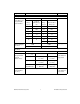
Specification Value Comments Voltage Levels Full Scale (FS) Input Range and Programmable Vertical Offset Maximum Input Overload 50 Ω 1 MΩ — Range (Vpk-pk) Vertical Offset Range (V) Range (Vpk-pk) Vertical Offset Range (V) 0.2 ±0.1 0.2 ±0.1 0.4 ±0.2 0.4 ±0.2 1 ±0.5 1 ±0.
Specification DC Drift Value Comments 50 Ω and 1 MΩ Range (Vpk-pk) — 0.2, 0.4, 1, and 2 ±(0.057% of Input + 0.006% of FS + 100 μV) per °C 4, 10, and 20 (1 MΩ only) ±(0.057% of Input + 0.006% of FS + 900 µV) per °C AC Amplitude Accuracy 50 Ω 1 MΩ ±0.06 dB (±0.7%) at 50 kHz ±0.09 dB (±1.
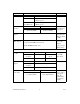
Specification AC Coupling Cutoff (–3 dB) Passband Flatness Value Comments 12 Hz Filter Settings Filters Off AC coupling available on 1 MΩ only Range (Vpk-pk) Referenced to 50 kHz 50 Ω and 1 MΩ All ranges except 0.2 ±0.5 dB DC to 20 MHz ±1.0 dB 20 MHz to 50 MHz 0.2 ±0.6 dB DC to 20 MHz ±1.7 dB 50 MHz to 100 MHz ±1.5 dB 20 MHz to 40 MHz Antialias Filter On All ranges –1.0 dB to +2.
Specification Value Comments Spectral Characteristics Spurious-Free Dynamic Range with Harmonics (SFDR) (Physical), Typical Range (Vpk-pk) 50 Ω 1 MΩ 0.2 75 dBc 70 dBc 0.
Specification Value Comments Intermodulation Distortion, Typical 0.2 Vpk-pk to 2.0 Vpk-pk Ranges on 50 Ω Input Filters off or antialias filter on –75 dBc Two tones at 10.2 MHz and 11.2 MHz Each tone is –7 dBFS Signal-to-Noise Ratio (SNR), Typical Signal to Noise and Distortion (SINAD), Typical 50 Ω 1 MΩ Range (Vpk-pk) Filters Off Antialias Filter On Filters Off Antialias Filter On 0.2 57 dB 56 dB 53 dB 55 dB 0.
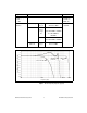
0 9.83 MHz, –1 dBFS Input Signal –10 –20 Amplitude (dBFS) –30 –40 –50 –60 –70 –80 –90 –100 –110 1M 10 M 20 M 30 M 40 M 50 M 60 M Frequency (Hz) 70 M 80 M 90 M 100 M Figure 2. NI 5124 Dynamic Performance, 50 Ω, 1 Vpk-pk Range, 262,144 Point FFT (Typical) NI PXI/PCI-5124 Specifications 8 ni.
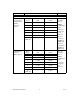
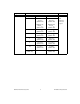
Specification RMS Noise Value Comments Range (Vpk-pk) 50 Ω 1 MΩ 0.2 NI PXI-5124: 94 μVrms (0.047% FS) NI PXI-5124: 104 μVrms (0.052% FS) NI PCI-5124: 106 μVrms (0.053% FS) NI PCI-5124: 116 μVrms (0.058% FS) 0.4 188 μVrms (0.047% FS) 192 μVrms (0.048% FS) 1 470 μVrms (0.047% FS) 480 μVrms (0.048% FS) 2 940 μVrms (0.047% FS) 960 μVrms (0.048% FS) 4 1.88 mVrms (0.047% FS) 1.92 mVrms (0.048% FS) 10 4.7 mVrms (0.047% FS) 4.8 mVrms (0.048% FS) 20 (1 MΩ only) — 9.4 mVrms (0.
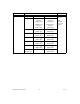
Specification RMS Noise Value Comments Range (Vpk-pk) 50 Ω 1 MΩ 0.2 NI PXI-5124: 112 μVrms (0.056% FS) NI PXI-5124: 130 μVrms (0.065% FS) NI PCI-5124: 126 μVrms (0.063% FS) NI PCI-5124: 146 μVrms (0.073% FS) 0.4 200 μVrms (0.05% FS) 216 μVrms (0.054% FS) 1 500 μVrms (0.05% FS) 510 μVrms (0.051% FS) 2 1.0 mVrms (0.05% FS) 1.02 mVrms (0.051% FS) 4 2.04 mVrms (0.051% FS) 2.16 mVrms (0.054% FS) 10 5.1 mVrms (0.051% FS) 5.2 mVrms (0.052% FS) 20 (1 MΩ only) N/A 10.2 mVrms (0.
Specification RMS Noise Value Comments Range (Vpk-pk) 50 Ω 1 MΩ Filters off 0.2 NI PXI-5124: 114 μVrms (0.057% FS) NI PXI-5124: 164 μVrms (0.082% FS) NI PCI-5124: 128 μVrms (0.064% FS) NI PCI-5124: 184 μVrms (0.092% FS) 50 Ω terminator connected to input 0.4 204 μVrms (0.051% FS) 264 μVrms (0.066% FS) 1 510 μVrms (0.051% FS) 550 μVrms (0.055% FS) 2 1.02 mVrms (0.051% FS) 1.08 mVrms (0.054% FS) 4 2.08 mVrms (0.052% FS) 2.6 mVrms (0.065% FS) 10 5.2 mVrms (0.052% FS) 5.5 mVrms (0.
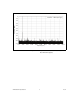
60 n 55 n Noise Density (nV/root Hz) 50 n 45 n 40 n 35 n 30 n 25 n 20 n 15 n 10 n 5n 1n 1k 10 k 100 k 1M 10 M 100 M Frequency (Hz) Figure 3. Representation of NI 5124 Spectral Noise Density on 0.2 V Range, Noise Filter Enabled, 1 MΩ Input Impedance Noise Density (dBm/Hz) –145.0 –147.5 –150.0 –152.5 1k 10 k 100 k 1M 10 M 100 M Frequency (Hz) Figure 4. Representation of NI 5124 Spectral Noise Density on 0.
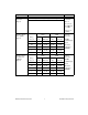
Horizontal Sample Clock Specification Value Sources NI PXI-5124 Comments NI PCI-5124 Internal, Onboard Clock (internal VCXO)* Internal, Onboard Clock (internal VCXO)* External, CLK IN (front panel SMB connector) External, CLK IN (front panel SMB connector) External, PXI Star Trigger (backplane connector) * Internal Sample Clock is locked to the Reference Clock or derived from the onboard VCXO Onboard Clock (Internal VCXO) Sample Rate Range * Divide Real-Time Sampling (Single Shot) Random Inter
Specification Sample Clock Jitter, Typical Value Comments ≤1 ps rms (100 Hz to 100 kHz) Includes the effects of the converter aperture uncertainty and the clock circuitry jitter ≤2 ps rms (100 Hz to 1 MHz) Excludes trigger jitter Timebase Frequency 200 MHz Timebase Accuracy — Not Phase-Locked to Reference Clock Phase-Locked to Reference Clock ±25 ppm — Equal to the Reference Clock accuracy Sample Clock Delay Range ±1 Sample Clock period — Sample Clock Delay/Adjustment Resolution ≤5 ps —
Specification Value Comments External Sample Clock Sources NI PXI-5124 NI PCI-5124 CLK IN (front panel SMB connector) — CLK IN (front panel SMB connector) PXI Star Trigger (backplane connector) Frequency Range 50 MHz to 210 MHz (CLK IN) 50 MHz to 80 MHz (PXI Star Trigger) Divide by n decimation available where 1 ≤ n ≤ 65,535 For more information about Sample Clock and decimation, refer to the NI High-Speed Digitizers Help.
Specification Value Comments Sample Clock Exporting * Decimated Exported Sample Clock Destinations Maximum Frequency Destination CLK OUT (front panel SMB connector) 210 MHz PXI_Trig<0..6> (backplane connector)* 20 MHz PFI<0..1> (front panel 9-pin mini-circular DIN connector)* 25 MHz RTSI<0..
CLK IN (Sample Clock and Reference Clock Input, Front Panel Connector) Specification Value Comments Input Voltage Range Sine wave: 0.65 Vpk-pk to 2.8 Vpk-pk (0 dBm to 13 dBm) Square wave: 0.2 Vpk-pk to 2.8 Vpk-pk — Maximum Input Overload 7 Vrms with |Peaks| ≤10 V — Impedance 50 Ω — Coupling AC — CLK OUT (Sample Clock and Reference Clock Output, Front Panel Connector) Specification Value Comments Output Impedance 50 Ω — Logic Type 3.
Specification Time Resolution Value TDC Onboard Clock External Clock On 50 ps N/A Off 5 ns External Clock Period Rearm Time Holdoff Comments TDC Rearm Time On 10 μs Off 2 μs TDC Onboard Clock External Clock On 10 μs to 85.899 s N/A Off 2 μs to 85.
Specification Value Trigger Filters Comments Low-Frequency (LF) Reject High-Frequency (HF) Reject 50 kHz 50 kHz — Digital Trigger (Digital Trigger Type) Sources NI PXI-5124 PXI_Trig<0..6> (backplane connector) PFI<0..1> (front panel SMB connector) NI PCI-5124 — RTSI<0..6> PFI<0..
PFI 0 and PFI 1 (Programmable Function Interface, AUX Front Panel Connector) Specification Value Comments Connector 9-pin mini-circular DIN — Direction Bi-directional — As an Input (Trigger) Destinations Start Trigger (Acquisition Arm) — Reference (Stop) Trigger Arm Reference Trigger Advance Trigger Input Impedance 150 kΩ — VIH 2.0 V — VIL 0.8 V — Maximum Input Overload –0.5 V, 5.
TClk Specifications National Instruments TClk synchronization method and the NI-TClk driver are used to align the sample clocks on any number of SMC-based modules in a chassis. For more information about TClk synchronization, refer to the NI-TClk Synchronization Help, which is located within the NI High-Speed Digitizers Help. • Specifications are valid for any number of modules installed in one NI PXI-1042 chassis. • All parameters set to identical values for each SMC-based module.
Waveform Specifications Specification Onboard Memory Size Value Comments * 8 MB per channel standard (4 megasamples per channel) NI PXI-5124 only 32 MB per channel option (16 megasamples per channel) 256 MB per channel option (128 megasamples per channel) 512 MB per channel option (256 megasamples per channel)* Minimum Record Length 1 Sample — Number of Pretrigger Samples Zero up to full Record Length Single-record mode and multiple-record mode Number of Posttrigger Samples Zero up to full Recor
Calibration Specification Value Comments Self-Calibration Self-calibration is done on software command. The calibration corrects for gain, offset, frequency response, triggering, and timing adjustment errors for all input ranges. — External Calibration (Factory Calibration) The external calibration calibrates the VCXO and the voltage reference. Appropriate constants are stored in nonvolatile memory.
Software Specification Value Driver Software NI-SCOPE 2.7 or later Application Software NI-SCOPE provides programming interfaces, documentation, and examples for the following application development environments: Comments — NI-SCOPE is an IVI-compliant driver that allows you to configure, control, and calibrate the NI 5124. NI-SCOPE provides application programming interfaces for many development environments.
Environment NI PXI-5124 Note To ensure that the NI PXI-5124 cools effectively, follow the guidelines in the Maintain Forced Air Cooling Note to Users included in the NI PXI-5124 kit. The NI PXI-5124 is intended for indoor use only.
NI PCI-5124 To ensure that the NI PCI-5124 cools effectively, make sure that the chassis in which it is used has active cooling that provides at least some airflow across the PCI card cage. To maximize airflow and extend the life of the device, leave any adjacent PCI slots empty. Refer to the Maintain Forced Air Cooling Note to Users included in the NI PCI-5124 kit for important cooling information. The NI PCI-5124 is intended for indoor use only.
Safety, Electromagnetic Compatibility, and CE Compliance Safety This product is designed to meet the requirements of the following standards of safety for electrical equipment for measurement, control, and laboratory use: • IEC 61010-1, EN 61010-1 • UL 61010-1, CSA 61010-1 Note For UL and other safety certifications, refer to the product label or visit ni.com/ certification, search by model number or product line, and click the appropriate link in the Certification column.
Environmental Management National Instruments is committed to designing and manufacturing products in an environmentally responsible manner. NI recognizes that eliminating certain hazardous substances from our products is beneficial not only to the environment but also to NI customers. For additional environmental information, refer to the NI and the Environment Web page at ni.com/environment.
NI PXI-5124 Front Panel Indicators Label Function ACCESS The ACCESS LED indicates the status of the PCI bus and the interface from the NI PXI-5124 to the controller. ACTIVE The ACTIVE LED indicates the status of the onboard acquisition hardware of the NI PXI-5124. For more information, refer to the NI High-Speed Digitizers Help. Dimensions and Weight NI PXI-5124 Dimensions 3U, One slot, PXI/cPCI Module 21.6 × 2.0 × 13.0 cm (8.5 × 0.8 × 5.1 in.) 2.0 cm (0.8 in.) 13.0 cm (5.1 in.) 21.6 cm (8.5 in.
NI PCI-5124 Dimensions 35.5 × 2.0 × 11.3 cm (14.0 × 0.8 × 4.4 in.) 2.0 cm (0.8 in.) 11.3 cm (4.4 in.) 35.5 cm (14.0 in.) Weight 455 g (16 oz) NI PXI/PCI-5124 Specifications 30 ni.
Where to Go for Support The National Instruments Web site is your complete resource for technical support. At ni.com/support you have access to everything from troubleshooting and application development self-help resources to email and phone assistance from NI Application Engineers. A Declaration of Conformity (DoC) is our claim of compliance with the Council of the European Communities using the manufacturer’s declaration of conformity.
National Instruments, NI, ni.com, and LabVIEW are trademarks of National Instruments Corporation. Refer to the Terms of Use section on ni.com/legal for more information about National Instruments trademarks. Other product and company names mentioned herein are trademarks or trade names of their respective companies. For patents covering National Instruments products, refer to the appropriate location: Help»Patents in your software, the patents.txt file on your CD, or ni.com/patents.