PXI Express NI PXIe-1075 User Manual NI PXIe-1075 User Manual July 2008 372537A-01
Support Worldwide Technical Support and Product Information ni.
Important Information Warranty The NI PXIe-1075 is warranted against defects in materials and workmanship for a period of one year from the date of shipment, as evidenced by receipts or other documentation. National Instruments will, at its option, repair or replace equipment that proves to be defective during the warranty period. This warranty includes parts and labor.
Contents About This Manual Conventions ...................................................................................................................vii Related Documentation..................................................................................................viii Chapter 1 Getting Started Unpacking ......................................................................................................................1-1 What You Need to Get Started ..........................................
Contents Installing Peripheral Modules........................................................................................ 2-9 Power Inhibit Switch LED Indicator............................................................................. 2-10 Remote Voltage Monitoring and Control...................................................................... 2-11 Inhibit Mode Switch ......................................................................................................
About This Manual The NI PXIe-1075 User Manual describes the features of the NI PXIe-1075 chassis and contains information about configuring the chassis, installing the modules, and operating the chassis. Conventions The following conventions are used in this manual: » The » symbol leads you through nested menu items and dialog box options to a final action. The sequence File»Page Setup»Options directs you to pull down the File menu, select the Page Setup item, and select Options from the last dialog box.
About This Manual Related Documentation The following documents contain information that you might find helpful as you read this manual: NI PXIe-1075 User Manual • IEEE 1101.1-1991, IEEE Standard for Mechanical Core Specifications for Microcomputers Using IEC 603-2 Connectors • IEEE 1101.10, IEEE Standard for Additional Mechanical Specifications for Microcomputers Using IEEE 1101.1 Equipment Practice • PICMG EXP.0 R1.
1 Getting Started This chapter describes the key features of the NI PXIe-1075 chassis and lists the kit contents and optional equipment you can order from National Instruments. Unpacking Carefully inspect the shipping container and the chassis for damage. Check for visible damage to the metal work. Check to make sure all handles, hardware, and switches are undamaged. Inspect the inner chassis for any possible damage, debris, or detached components.
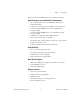
Chapter 1 Getting Started Table 1-1. AC Power Cables Power Cable Reference Standards Standard 120 V, 15 A (USA) NEMA 5-15 (gray color) Switzerland 220 V SEV Australia 240 V AS C112 Universal Euro 230 V CEE (7), II, IV, VII IEC83 North America 120 V, 15 A NEMA 5-15 (gray color) United Kingdom 230 V BS 1363/IEC83 Japan 100 V, 15 A JIS C8303 (gray color) For 100–120 VAC installation, use the NI cable part numbers listed in Table 1-2, which are rated for 125 V/15 A. Table 1-2.
Chapter 1 Getting Started The key features of the NI PXIe-1075 chassis include the following: High Performance for Instrumentation Requirements • Up to 1 GB/s (single direction) per PXI Express slot dedicated bandwidth (x4 PCIe) • 38 W per slot cooling meets increased PXIe cooling requirements • Low-jitter internal 10 MHz reference clock for PXI slots with ± 25 ppm stability • Low-jitter internal 100 MHz reference clock for PXIe slots with ± 25 ppm stability • 8 hybrid slots for supporting exist
Chapter 1 Getting Started Chassis Description Figures 1-1 and 1-2 show the key features of the NI PXIe-1075 chassis front and back panels. Figure 1-1 shows the front view of the NI PXIe-1075. Figure 1-2 shows the rear view of the NI PXIe-1075.
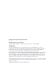
Chapter 1 4 3 6 5 7 8 9 Getting Started 10 2 11 1 12 4 1 2 3 4 5 6 7 Universal AC Input Push-Reset Circuit Breaker Chassis Ground Screw Air Filter Retainer Screws Power Supply Shuttle ID Label 10 MHz REF OUT BNC 10 MHz REF IN BNC 14 8 9 10 11 12 13 14 13 Remote Inhibit and Voltage Monitoring Connector Inhibit Mode Selector Switch Fan Speed Selector Switch Power Supply Shuttle Mounting Screws (10x) Power Supply Shuttle Handle (2x) Power Supply Shuttle Air Filter Retainer Figure 1-2.
Chapter 1 Getting Started Slot Blockers Optional slot blocker kits are available from National Instruments for improved thermal performance when all slots are not used. NI PXIe-1075 Chassis Backplane Overview This section provides an overview of the backplane features for the NI PXIe-1075 chassis.
Chapter 1 Getting Started System Controller Slot The system controller slot is Slot 1 of the chassis and is a 4-Link configuration system slot as defined by the CompactPCI Express and PXI Express specifications. It has three system controller expansion slots for system controller modules that are wider than one slot. These slots allow the system controller to expand to the left to prevent the system controller from using peripheral slots.
Chapter 1 Getting Started PXI Express Peripheral Slots There are eight (8) PXI Express peripheral slots: slots 6–9 and 11–14 (=8 slots). PXI Express peripheral slots can accept the following modules: • A PXI Express Peripheral with x4 or x1 PCI Express link to the system slot or through a PCIe switch to the system slot. • A CompactPCI Express Type-2 Peripheral with x4 or x1 PCI Express link to the system slot or through a PCIe switch to the system slot.
Chapter 1 Getting Started PXI Star 8 PXI Star 7 PXI Star 17 PXI Star 6 PXI Star 16 PXI Star 5 PXI Star 15 PXI Star 4 PXI Star 14 PXI Star 3 PXI Star 13 PXI Star 2 PXI Star 12 PXI Star 1 PXI Star 11 PXI Star 0 PXI Star 10 PXIe_DStar 8 PXIe_DStar 0 PXIe_DStar 9 PXIe_DStar 1 PXIe_DStar 2 PXIe_DStar 10 PXIe_DStar 3 PXIe_DStar 11 PXIe_DStar 12 PXIe_DStar 4 PXIe_DStar 16 PXIe_DStar 7 PXIe_DStar 13 PXIe_DStar 5 PXIe_DStar 14 PXIe_DStar 6 PXIe_DStar 15 H 1 2 H 3 H 4 H 5 H 6 7 8
Chapter 1 Getting Started The PXI trigger lines from adjacent PXI trigger bus segments can be routed in either direction across the PXI trigger bridges. Refer to Figure 1-5 for the connectivity diagram. This allows you to send trigger signals to, and receive trigger signals from, every slot in the chassis. Static trigger routing (user-specified line and directional assignments) can be configured through Measurement & Automation Explorer (MAX).
Chapter 1 Getting Started An independent buffer drives PXIe_CLK100 to each peripheral slot. These clocks are matched in skew to less than 100 ps. The differential pair must be terminated on the peripheral with LVPECL termination for the buffer to drive PXIe_CLK100 so that when there is no peripheral or a peripheral that does not connect to PXIe_CLK100, there is no clock being driven on the pair to that slot. Refer to Figure 1-6 for a termination example. CLK100 + + CLK100 – – 50 Ω 50 Ω 47 Ω 0.
Chapter 1 Getting Started To synchronize the system to an external clock, you can drive PXI_CLK10 from an external source through the PXI_CLK10_IN pin on the System Timing Slot. Refer to Table B-5, XP4 Connector Pinout for the System Timing Slot, for the pinout. When a 10MHz clock is detected on this pin, the backplane automatically phase-locks the PXI_CLK10, PXIe_CLK100, and PXIe_SYNC100 signals to this external clock and distributes these signals to the slots.
Chapter 1 Getting Started A copy of the backplane’s PXI_CLK10 is exported to the 10 MHz REF OUT connector on the rear of the chassis. Refer to Figure 1-2 for the location of this connector. This clock is driven by an independent buffer. Refer to Appendix A, Specifications, for the specification information for the 10 MHz REF OUT signal on the rear panel of the chassis. PXIe_SYNC_CTRL PXIe_SYNC100 is by default a 10 ns pulse synchronous to PXI_CLK10.
Installation and Configuration 2 This chapter describes how to prepare and operate the NI PXIe-1075 chassis. Before connecting the chassis to a power source, read this chapter and the Read Me First: Safety and Radio-Frequency Interference document included with your kit. Safety Information Before undertaking any troubleshooting, maintenance, or exploratory procedure, carefully read the following caution notices.
Chapter 2 Installation and Configuration • Part Replacement—Only service this equipment with parts that are exact replacements, both electrically and mechanically. Contact National Instruments for replacement part information. Installation of parts with those that are not direct replacements may cause harm to personnel operating the chassis. Furthermore, damage or fire may occur if replacement parts are unsuitable. • Modification—Do not modify any part of the chassis from its original condition.
Chapter 2 Dimensions are in inches (millimeters) Installation and Configuration 1.75 (44.45) 1.75 (44.45) NI PXIe-1075 3.00 (76.20) Figure 2-1.
Chapter 2 Installation and Configuration 2 3 1 4 1 2 3 Primary Air Exhaust Vent Air Filter Primary Air Intake Vent 3 Secondary Air Intake/Exhaust Vents (both sides) Figure 2-2. NI PXIe-1075 Vents Chassis Ambient Temperature Definition The chassis fan control system uses intake air temperature as the input for controlling fan speeds when in Auto Fan Speed mode.
Chapter 2 Installation and Configuration responsibility to ensure that this ambient temperature does not exceed the rated ambient temperature as stated in Appendix A, Specifications. If the temperature exceeds the stated spec the power switch LED will blink green, as discussed in the Power Inhibit Switch LED Indicator section of this chapter. Setting Fan Speed The fan-speed selector switch is on the rear panel of the NI PXIe-1075 chassis.
Chapter 2 Installation and Configuration If your power outlet does not have an appropriate ground connection, you must connect the premise safety ground to the chassis grounding screw located on the rear panel. Refer to Figure 1-2, Rear View of the NI PXIe-1075 Chassis, to locate the chassis grounding screw. To connect the safety ground, complete the following steps: 1. Connect a 16 AWG (1.3 mm) wire to the chassis grounding screw using a grounding lug.
Chapter 2 3. Installation and Configuration Install the system controller into the system controller slot (slot 1, indicated by the red card guides) by first placing the system controller PCB into the front of the card guides (top and bottom). Slide the system controller to the rear of the chassis, making sure that the injector/ejector handle is pushed down as shown in Figure 2-3.
Chapter 2 Installation and Configuration Figure 2-4 shows a PXI Express system controller installed in the system controller slot of a NI PXIe-1075 chassis. You can place CompactPCI, CompactPCI Express, PXI, or PXI Express modules in other slots depending on the slot type. 1 2 NI PX Ie10 75 3 1 NI PXIe-1075 Chassis 2 NI PXIe System Controller 3 Injector/Ejector Rail Figure 2-4. NI PXI Express System Controller Installed in a NI PXIe-1075 Chassis NI PXIe-1075 User Manual 2-8 ni.
Chapter 2 Installation and Configuration Installing Peripheral Modules The NI PXIe-1075 chassis has been designed to accept a variety of peripheral module types in different slots. To prevent damage to the chassis, ensure that the peripheral module is being installed into a slot designed to accept it. Refer to Chapter 1, Getting Started, for a description of the various slot types.
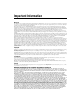
Chapter 2 Installation and Configuration 3 2 NI PX Ie- 10 75 1 6 4 5 1 2 3 Peripheral Module Front Panel Mounting Screws (2x) NI PXI Express System Controller NI PXIe-1075 Chassis 4 5 6 Injector/Ejector Rail Injector/Ejector Handle PXI Express Peripheral Module Figure 2-5. Installing PXI, PXI Express, or CompactPCI Peripheral Modules Power Inhibit Switch LED Indicator The chassis power inhibit switch has an integrated LED.
Chapter 2 Installation and Configuration If two system fans or both of the power supply fans fail the chassis will shut down automatically, preventing the chassis and modules from damage due to overheating. Note Remote Voltage Monitoring and Control The NI PXIe-1075 chassis supports remote voltage monitoring and inhibiting through a female 9-pin D-SUB (DB-9) connector located on the rear panel as shown in Figure 1-2, Rear View of the NI PXIe-1075 Chassis.
Chapter 2 Installation and Configuration You can use a digital voltmeter to ensure all voltage levels in the NI PXIe-1075 chassis are within the allowable limits. Referring to Table 2-2, connect one lead of the voltmeter to a supply pin on the remote voltage monitoring connector (9-pin D-SUB) on the rear panel. Refer to Table 2-1 for a pinout diagram of the remote voltage monitoring connector. Connect the reference lead of the voltmeter to one of the ground pins.
Chapter 2 Installation and Configuration (pin 5) to a Logic Ground pin (pin 1 or 9). As long as this connection exists, the chassis will remain off (standby); when you remove this connection, the chassis turns on. Note For the Remote Inhibit signal to control the On/Off (standby) state of the chassis, the Inhibit Mode switch must be in the Manual position.
Chapter 2 Installation and Configuration Figure 2-6. Multichassis Configuration in MAX PXI-1 System Configuration NI PXIe-1075 User Manual 1. Launch MAX. 2. In the Configuration tree, click the Devices and Interfaces branch to expand it. 3. If the PXI system controller has not yet been configured, it is labeled PXI System (Unidentified). Right-click this entry to display the pop-up menu, then select the appropriate system controller model from the Identify As submenu. 2-14 ni.
Chapter 2 4. Installation and Configuration Click the PXI system controller. The chassis (or multiple chassis, in a multichassis configuration) is listed below it. Identify each chassis by right-clicking its entry, then selecting the appropriate chassis model through the Identify As submenu. Further expanding the PXI System branch shows all devices in the system that can be recognized by NI-VISA. When your system controller and all your chassis are identified, the required pxisys.ini or pxiesys.
Chapter 2 Installation and Configuration Complete the following steps to reserve these trigger lines in MAX. 1. In the Configuration tree, click on the PXI chassis branch you want to configure. 2. Then, in the right-hand pane, toward the bottom, click on the Triggers tab. 3. Select which trigger lines you would like to statically reserve. 4. Click the Apply button.
Chapter 2 Installation and Configuration The capability documentation for the NI PXIe-1075 chassis is contained in the chassis.ini file on the software media that comes with the chassis. The information in this file is combined with information about the system controller to create a single system initialization file called pxisys.ini (PXI System Initialization). The system controller manufacturer either provides a pxisys.
3 Maintenance This chapter describes basic maintenance procedures you can perform on the NI PXIe-1075 chassis. Caution Disconnect the power cable prior to servicing a NI PXIe-1075 chassis. Service Interval Clean the chassis fan filters at a maximum interval of six months. Depending on the amount of use and ambient dust levels in the operating environment, the filters may require more frequent cleaning. Clean dust from the chassis exterior (and interior) as needed, based on the operating environment.
Chapter 3 Maintenance Caution Always disconnect the AC power cable before cleaning or servicing the chassis. Interior Cleaning Use a dry, low-velocity stream of air to clean the interior of the chassis. Use a soft-bristle brush for cleaning around components. Exterior Cleaning Clean the exterior surfaces of the chassis with a dry lint-free cloth or a soft-bristle brush. If any dirt remains, wipe with a cloth moistened in a mild soap solution.
Chapter 3 Maintenance Resetting the AC Mains Circuit Breaker If the NI PXIe-1075 chassis is connected to an AC source and encounters an over-current condition, the circuit breaker on the rear panel will trip to prevent damage to the chassis. Complete the following steps to reset the circuit breaker. 1. Turn off the chassis. 2. Disconnect the AC power cable. 3. Depress the circuit breaker to reset it. 4. Reconnect the AC power cable. 5. Turn on the chassis.
Chapter 3 Maintenance Before connecting the power supply shuttle to a power source, read this section and the Read Me First: Safety and Radio-Frequency Interference document included with the kit. Removal The NI PXIe-1075 AC power supply shuttle is a replacement part for the NI PXIe-1075 AC chassis. Before attempting to replace the power supply shuttle, verify that there is adequate clearance behind the chassis. Disconnect the power cable from the power supply shuttle on the back of the chassis.
A Specifications This appendix contains specifications for the NI PXIe-1075 chassis. Caution Specifications are subject to change without notice. Electrical AC Input Input voltage rating ................................ 100 to 120 VAC, 220 to 240 VAC Operating voltage range1 ........................ 90 to 120 VAC, 200 to 264 VAC Input current rating................................. 12 A, 6 A Input frequency ...................................... 50/60 Hz Over-current protection..........................
Appendix A Specifications Power disconnect ....................................The AC power cable provides main power disconnect. The front-panel power switch causes the internal chassis power supply to provide DC power to the CompactPCI/PXI Express backplane. You also can use the rear-panel D-SUB 9-pin connector and power mode switch to control the internal chassis power supply. For more information, refer to the Inhibit Mode Switch section of Chapter 2, Installation and Configuration.
Appendix A Specifications Backplane pin current capacity Slot +5 V V (I/O) +3.3 V +12 V –12 V 5 VAUX System Controller Slot 9A 0A 9A 11 A 0A 1A System Timing Slot 0A 0A 3A 2A 0A 1A Hybrid Peripheral Slot with PXI-1 Peripheral 6A 5A 6A 1A 1A 0A Hybrid Peripheral Slot with PXI-5 Peripheral 0A 0A 3A 3A 0A 1A PXI-1 Peripheral Slot 6A 11 A 6A 1A 1A 0A Load regulation Voltage Load Regulation +3.
Appendix A Specifications Chassis Cooling Module cooling system...........................Forced air circulation (positive pressurization) through three 165 cfm fans with High/Auto speed selector Slot airflow direction ..............................Bottom of module to top of module Module cooling intake ............................Bottom rear of chassis Module cooling exhaust..........................Along both sides and top of chassis Power supply cooling system .................
Appendix A Specifications Operating Environment Ambient temperature range.................... 0 to 55 °C (Tested in accordance with IEC-60068-2-1 and IEC-60068-2-2. Meets MIL-PRF-28800F Class 3 low temperature limit and MIL-PRF-28800F Class 2 high temperature limit.) Relative humidity range ......................... 10 to 90%, noncondensing (Tested in accordance with IEC-60068-2-56.) Storage Environment Ambient temperature range....................
Appendix A Specifications Sound Power Auto fan (up to ~30 °C ambient) ............55.5 dBA High fan ..................................................76.2 dBA Notes For EMC compliance, operate this device with shielded cabling. In addition, all covers and filler panels must be installed. Refer to the Declaration of Conformity (DoC) for this product for any additional regulatory compliance information. To obtain the DoC for this product, visit ni.
Appendix A Specifications CE Compliance This product meets the essential requirements of applicable European Directives, as amended for CE marking, as follows: • 2006/95/EC; Low-Voltage Directive (safety) • 2004/108/EC; Electromagnetic Compatibility Directive (EMC) Refer to the Declaration of Conformity (DoC) for this product for any additional regulatory compliance information. To obtain the DoC for this product, visit ni.
Appendix A Specifications Backplane Size .........................................................3U-sized; one system slot (with three system expansion slots) and 17 peripheral slots. Compliant with IEEE 1101.10 mechanical packaging. PXI Express Specification compliant. Accepts both PXI Express and CompactPCI (PICMG 2.0 R 3.0) 3U modules. Backplane bare-board material ...............UL 94 V-0 Recognized Backplane connectors .............................
Appendix A Specifications 100 MHz System Reference Clock: PXIe_CLK100 and PXIe_SYNC100 Maximum slot-to-slot skew ................... 100 ps Accuracy ................................................ ±25 ppm max. (guaranteed over the operating temperature range) Maximum jitter ...................................... 3 ps RMS phase-jitter (10 Hz–12 kHz range) 2 ps RMS phase-jitter (12 kHz–20 MHz range) Duty-factor for PXIe_CLK100 ..............
Appendix A Specifications External Clock Source Frequency ...............................................10 MHz ±100 PPM Input amplitude Rear panel BNC...............................200 mVPP to 5 VPP square-wave or sine-wave System timing slot PXI_CLK10_IN ..............................5 V or 3.3 V TTL signal Rear panel BNC input impedance ..........50 Ω ±5 Ω Maximum jitter introduced by backplane ...........................................1 ps RMS phase-jitter (10 Hz–1 MHz range) PXIe_SYNC_CTRL VIH ....
Appendix A Specifications Notes For PXIe slot to PXI_DSTAR mapping refer to the System Timing Slot section of Chapter 1, Getting Started. For other specifications, the NI PXIe-1075 complies with the PXI-5 PXI Express Hardware Specification. Mechanical Overall dimensions Standard chassis Height ...................................... 6.97 in. (177.1 mm) Width ....................................... 18.30 in. (464.8 mm) Depth ....................................... 18.40 in. (467.4 mm) 0.57 in. (14.
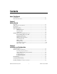
Appendix A Specifications Dimensions are in inches (millimeters) .39 (9.9) 17.54 (445.6) NI PXIe-1075 6.97 (177.1) 0.57 (14.5) 1.82 1.14 (29.1) (46.3) 1.82 (46.3) 1.37 (34.8) 1.58 (40.1) 10.21 (259.1) Front of PXI Card 1.84 3.54 (46.8) (90.0) 0.30 (7.25) 2.12 (53.8) 17.11 (434.6) 3.19 (81.1) Figure A-1. NI PXIe-1075 Chassis Dimensions (Front and Side) NI PXIe-1075 User Manual A-12 ni.
Appendix A Specifications Dimensions are in inches (millimeters) 12.700 (322.58) 2.524 (64.11) 15.504 (393.8) 1.017 (25.83) Figure A-2.
Appendix A Specifications Figure A-3 shows the chassis rack mount kit components. 2 NI PX Ie- 10 75 3 1 1 Front Rack Mount Kit 2 NI Chassis 3 Optional Rear Rack Mount Kit Figure A-3. NI Chassis Rack Mount Kit Components Notes The chassis shown in Figure A-3 is representative of the NI PXI-1044/1045 and NI PXIe-1075 product line. For more information on rack mounting the NI PXIe-1075 chassis, refer to the printed installation guide included with your rack mount kit.
B Pinouts This appendix describes the connector pinouts for the NI PXIe-1075 chassis backplane. Figure B-1 illustrates the types of PXIe connectors by providing a layout of the PXI Express system controller slot (slot 1). Table B-1 shows the XP4 Connector Pinout for the System Controller slot. Table B-2 shows the XP3 Connector Pinout for the System Controller slot. Table B-3 shows the XP2 Connector Pinout for the System Controller slot.
Appendix B Pinouts System Controller Slot Pinouts 1 2 3 4 1 2 XP4 Connector XP3 Connector 3 4 XP2 Connector XP1 Connector Figure B-1. PXI Express System Controller Slot Layout Table B-1.
Appendix B Pinouts Table B-2.
Appendix B Pinouts Table B-4. XP1 Connector Pinout for the System Controller Slot Pins Signals A GND B 12V C 12V D GND E 5V F 3.3V G GND System Timing Slot Pinouts 1 2 3 4 1 2 XP4 Connector XP3 Connector 3 4 TP2 Connector TP1 Connector Figure B-2. PXI Express System Timing Slot Layout NI PXIe-1075 User Manual B-4 ni.
Appendix B Pinouts Table B-5. XP4 Connector Pinout for the System Timing Slot Pin Z A B C D E F 1 GND GA4 GA3 GA2 GA1 GA0 GND 2 GND 5Vaux GND SYSEN# WAKE# ALERT# GND 3 GND 12V 12V GND GND GND GND 4 GND GND GND 3.3V 3.3V 3.
Appendix B Pinouts Table B-7.
Appendix B Pinouts Table B-8.
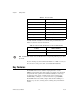
Appendix B Pinouts Hybrid Slot Pinouts 1 2 3 1 XP4 Connector 2 XP3 Connector 3 P1 Connector Figure B-3. PXI Express System Hybrid Slot Layout Table B-9. XP4 Connector Pinout for the Hybrid Slot Pin Z A B C D E F 1 GND GA4 GA3 GA2 GA1 GA0 GND 2 GND 5Vaux GND SYSEN# WAKE# ALERT# GND 3 GND 12V 12V GND GND GND GND 4 GND GND GND 3.3V 3.3V 3.
Appendix B Pinouts Table B-10.
Appendix B Pinouts Table B-11. P1 Connector Pinout for the Hybrid Slot Pin Z A B C D E F 25 GND 5V REQ64# ENUM# 3.3V 5V GND 24 GND AD[1] 5V V(I/O) AD[0] ACK64# GND 23 GND 3.3V AD[4] AD[3] 5V AD[2] GND 22 GND AD[7] GND 3.3V AD[6] AD[5] GND 21 GND 3.3V AD[9] AD[8] M66EN C/BE[0]# GND 20 GND AD[12] GND V(I/O) AD[11] AD[10] GND 19 GND 3.3V AD[15] AD[14] GND AD[13] GND 18 GND SERR# GND 3.3V PAR C/BE[1]# GND 17 GND 3.
Technical Support and Professional Services C Visit the following sections of the award-winning National Instruments Web site at ni.com for technical support and professional services: • Support—Technical support resources at ni.com/support include the following: – Self-Help Technical Resources—For answers and solutions, visit ni.
Appendix C Technical Support and Professional Services • Declaration of Conformity (DoC)—A DoC is our claim of compliance with the Council of the European Communities using the manufacturer’s declaration of conformity. This system affords the user protection for electromagnetic compatibility (EMC) and product safety. You can obtain the DoC for your product by visiting ni.com/certification. If you searched ni.
Glossary Symbol Prefix Value p pico 10 –12 n nano 10 –9 μ micro 10 – 6 m milli 10 –3 k kilo 10 3 M mega 10 6 G giga 10 9 T tera 10 12 Symbols ° Degrees. ≥ Equal or greater than. ≤ Equal or less than. % Percent. A A Amperes. AC Alternating current. ANSI American National Standards Institute. Auto Automatic fan speed control. AWG American Wire Gauge.
Glossary B backplane An assembly, typically a printed circuit board, with connectors and signal paths that bus the connector pins. BNC Bayonet Neill Concelman connector; a commonly used coaxial connector. C C Celsius. cfm Cubic feet per minute. CFR Code of Federal Regulations. cm Centimeters. CompactPCI An adaptation of the Peripheral Component Interconnect (PCI) Specification 2.
Glossary E efficiency Ratio of output power to input power, expressed as a percentage. EIA Electronic Industries Association. EMC Electromagnetic Compatibility. EMI Electromagnetic Interference. F FCC Federal Communications Commission. filler panel A blank module front panel used to fill empty slots in the chassis. G g (1) grams; (2) a measure of acceleration equal to 9.8 m/s2. GPIB General Purpose Interface Bus (IEEE 488). gRMS A measure of random vibration.
Glossary in. Inches. inhibit To turn off. J jitter A measure of the small, rapid variations in clock transition times from their nominal regular intervals. Units: seconds RMS. K kg Kilograms. km Kilometers. L lb Pounds. LED Light emitting diode. line regulation The maximum steady-state percentage that a DC voltage output will change as a result of a specified change in input AC voltage (step change from 90 to 132 VAC or 180 to 264 VAC).
Glossary N NEMA National Electrical Manufacturers Association. NI National Instruments. P power supply shuttle A removable module that contains the chassis power supply. PXI PCI eXtensions for Instrumentation. PXI_CLK10 10 MHz PXI system reference clock. R RH Relative humidity. RMS Root mean square. S s Seconds. skew Deviation in signal transmission times. slot blocker An assembly installed into an empty slot to improve the airflow in adjacent slots.
Glossary system reference clock A 10 MHz clock, also called PXI_CLK10, that is distributed to all peripheral slots in the chassis, as well as a BNC connector on the rear of chassis labeled 10 MHz REF OUT. The system reference clock can be used for synchronization of multiple modules in a measurement or control system. The 10 MHz REF IN and OUT BNC connectors on the rear of the chassis can be used to synchronize multiple chassis to one reference clock.
Index A clearances for chassis cooling, 2-2 figure, 2-3 CLK10 rear connectors, 2-13 CompactPCI interoperability with NI PXIe-1075 backplane, 1-6 configuration in MAX (figure), 2-14 configuration. See installation, configuration, and operation connector pinouts.
Index F setting fan speed, 2-5 site considerations, 2-2 slot blocker installation, 2-5 testing power up, 2-6 unpacking the PXIe-1075, 1-1 installing a PXI Express system controller (figure), 2-7 instrument drivers (NI resources), C-1 interoperability with CompactPCI, 1-6 fan, setting speed, 2-5 filler panel installation, 2-5 G ground, connecting, 2-5 H help, technical support, C-1 hybrid peripheral slots, description, 1-7 hybrid slot pinouts P1 connector (table), B-10 XP3 connector (table), B-9 XP4 con
Index power supply connecting to, 2-6 remote voltage monitoring and inhibiting interface, 2-11 replacing, 3-3 configuration, 3-4 connecting safety ground, 3-4 connecting to power source, 3-4 installation, 3-4 removal, 3-4 voltages at voltage monitoring connector (DB-9) (table), 2-11 power up, testing, 2-6 programming examples (NI resources), C-1 PXI differential star trigger specifications (PXIe-DSTARA, PXIe-DSTARB, PXIe-DSTARC), A-10 PXI Express configuration in MAX, 2-13 PXI Express peripheral slots, des
Index S rack mount kit dimensions (figure), A-14 safety, A-6 shock and vibration, A-5 system reference clocks, A-8 static discharge damage (caution), 3-1 support, technical, C-1 system controller slot description, 1-7 pinouts XP1 connector (table), B-4 XP2 connector (table), B-3 XP3 connector (table), B-3 XP4 connector (table), B-2 system reference clock, 1-10 default behavior (figure), 1-11 specifications, A-8 system timing slot description, 1-8 pinouts TP1 connector (table), B-7 TP2 connector (table), B
Index V W voltage monitoring connector.