PXI Express NI PXIe-6672 User Manual Timing and Synchronization Module for PXI Express NI PXIe-6672 User Manual June 2008 372185F-01
Support Worldwide Technical Support and Product Information ni.
Important Information Warranty The NI PXIe-6672 is warranted against defects in materials and workmanship for a period of one year from the date of shipment, as evidenced by receipts or other documentation. National Instruments will, at its option, repair or replace equipment that proves to be defective during the warranty period. This warranty includes parts and labor.
Contents About This Manual Conventions ...................................................................................................................vii National Instruments Documentation ............................................................................viii Related Documentation..................................................................................................viii Chapter 1 Introduction What You Need to Get Started .............................................................
Contents Choosing the Type of Routing ........................................................................ 3-15 Asynchronous Routing ..................................................................... 3-16 Synchronous Routing ....................................................................... 3-17 Generating a Single Pulse (Global Software Trigger) .................................... 3-18 Using the PXI_CLK10 PLL ....................................................................................
About This Manual Thank you for purchasing the National Instruments NI PXIe-6672 Timing and Synchronization Module. The NI PXIe-6672 enables you to pass PXI timing and trigger signals between two or more PXI Express chassis. The NI PXIe-6672 can generate and route clock signals between devices in multiple chassis, providing a method to synchronize multiple devices in a multichassis PXI Express system.
About This Manual monospace Text in this font denotes text or characters that you should enter from the keyboard, sections of code, programming examples, and syntax examples. This font is also used for the proper names of disk drives, paths, directories, programs, subprograms, subroutines, device names, functions, operations, variables, filenames, and extensions. NI PXIe-6672 This phrase refers to the NI PXIe-6672 module for the PXI Express bus.
1 Introduction The NI PXIe-6672 timing and triggering module enables you to pass PXI timing signals between two or more PXI Express chassis. The NI PXIe-6672 module generates and routes clock signals between devices in multiple chassis, providing a method for synchronizing multiple devices in a PXI Express system.
Chapter 1 Introduction Unpacking The NI PXIe-6672 is shipped in an antistatic package to prevent electrostatic damage to the module. Electrostatic discharge (ESD) can damage several components on the module. Caution Never touch the exposed pins of connectors. To avoid such damage in handling the module, take the following precautions: • Ground yourself using a grounding strap or by touching a grounded object.
Chapter 1 Introduction Safety Information The following section contains important safety information that you must follow when installing and using the product. Do not operate the product in a manner not specified in this document. Misuse of the product can result in a hazard. You can compromise the safety protection built into the product if the product is damaged in any way. If the product is damaged, return it to National Instruments for repair.
Chapter 1 Introduction Operate the product at or below the installation category1 marked on the hardware label. Measurement circuits are subjected to working voltages2 and transient stresses (overvoltage) from the circuit to which they are connected during measurement or test. Installation categories establish standard impulse withstand voltage levels that commonly occur in electrical distribution systems.
Installing and Configuring 2 This chapter describes how to install the NI PXIe-6672 hardware and software and how to configure the device. Installing the Software Refer to the readme.htm file that accompanies the NI-Sync CD for software installation directions. Note Be sure to install the driver software before installing the NI PXIe-6672 hardware. Installing the Hardware The following are general installation instructions.
Chapter 2 Installing and Configuring Note The slot number printed on the glyph may vary from chassis to chassis. The circle inside of the square indicates that the slot may also be used as a PXI Express peripheral slot. 3. Remove the filler panel for the PXI slot you located in step 2. 4. Ground yourself using a grounding strap or by holding a grounded object. Follow the ESD protection precautions described in the Unpacking section of Chapter 1, Introduction. 5.
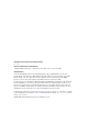
3 Hardware Overview This chapter presents an overview of the hardware functions of the NI PXIe-6672. Figure 3-1 provides a functional overview of the NI PXIe-6672 hardware.
Chapter 3 CLKIN Hardware Overview PXI_CLK10_IN AC Coupled Clock Detector PLL TCXO Calibration DAC PXI_CLK10 PXI TCXO Clock TCXO CLKOUT CLKIN DDS DDS Clock PFI 0 Driver/ Comparator CLOCK and TRIGGER Routing PFI 0 Threshold DAC PFI 1 PXI_STAR<0..16> PXI_TRIG<0..
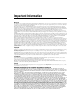
Chapter 3 Hardware Overview NI PXIe-6672 Front Panel Figure 3-2 shows the connectors and LEDs on the front panel of the NI PXIe-6672. NI PXIe-6672 Timing Module 1 2 ACCESS ACTIVE 3 CLK OUT 4 CLK IN PFI 0 PFI 1 PFI 2 5 PFI 3 PFI 4 PFI 5 1 2 3 Access LED Active LED CLKOUT Connector 4 5 CLKIN Connector PFI <0..5> Connectors Figure 3-2.
Chapter 3 Hardware Overview Access LED The Access LED indicates the communication status of the NI PXIe-6672. Refer to Figure 3-2 for the location of the Access LED. Table 3-1 summarizes what the Access LED colors represent. Table 3-1. Access LED Color Indication Color Status Off Module is not yet functional. Green Driver has initialized the module. Amber Module is being accessed. The Access LED flashes amber for 50 ms when the module is accessed.
Chapter 3 Hardware Overview Connectors This section describes the connectors on the front panel of the NI PXIe-6672. • CLKIN—Clock Input. This connector supplies the module with a clock that can be programmatically routed to the onboard PLL for use as a reference or routed directly to the PXI backplane (PXI_CLK10_IN) for distribution to the other modules in the chassis. • CLKOUT—Clock Output.
Chapter 3 Hardware Overview Table 3-3 outlines the function and direction of the signals discussed in detail in the remainder of this chapter. Table 3-3. Signal Descriptions Signal Name Direction Description Out This is a signal that can replace the native 10 MHz oscillator on the PXI backplane. PXI_CLK10_IN may originate from the onboard TCXO or from an external source. PXI_CLK10 In This signal is the PXI 10 MHz backplane clock.
Chapter 3 Hardware Overview The remainder of this chapter describes how these signals are used, acquired, and generated by the NI PXIe-6672 hardware, and explains how you can route the signals between various locations to synchronize multiple measurement devices and PXI chassis. Clock Generation The NI PXIe-6672 can generate two types of clock signals. The first clock is generated using the onboard DDS chip, and the second is generated with a precise 10 MHz oscillator.
Chapter 3 Hardware Overview of the PXI trigger lines is used as the source for the update, frequency generation will not start until a rising edge occurs on the PXI trigger selected. NI-Sync software defaults to an immediate update. If a PXI trigger is used instead, the user must specify the update signal source before setting any of the other DDS properties. Note When more then one NI PXIe-6672 is used in a multiple chassis setup, the DDS frequency of both boards can be synchronized.
Chapter 3 Hardware Overview clock; this feature must be explicitly enabled in software. The TCXO output also can be routed out to the CLKOUT connector. In addition to replacing the native backplane clock directly, the TCXO can phase lock to an external frequency source. This operation is discussed in detail in the Using the PXI_CLK10 PLL section. Routing Signals The NI PXIe-6672 has versatile trigger routing capabilities.
Chapter 3 Hardware Overview Figures 3-3 and 3-4 summarize the routing features of the NI PXIe-6672. The remainder of this chapter details the capabilities and constraints of the routing architecture. PFI 0 Selection Circuitry PFI 1 Selection Circuitry PFI 5 Selection Circuitry * PXI_STAR<0..16>, 28 PXI_TRIG<0..7>, PFI<0..5>, and Software Trigger are routed to SOURCE of each Selection Circuitry block.
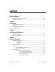
Chapter 3 Hardware Overview Figure 3-4 provides a more detailed view of the Selection Circuitry referenced in Figure 3-3. CLKIN* SOURCE PFI<0..5> PXI_TRIG<0..7> PXI_STAR<0..16> Software Trigger DESTINATION SYNCHRONIZATION CLOCKS GND CLK CLK/N CLK/M * CLKIN only valid for PXI_STAR Figure 3-4. Signal Selection Circuitry Diagram Determining Sources and Destinations All signal routing operations can be characterized by a source (input) and a destination.
Chapter 3 Hardware Overview Table 3-4 summarizes the sources and destinations of the NI PXIe-6672. The destinations are listed in the horizontal heading row, and the sources are listed in the column at the far left. A ✓ in a cell indicates that the source and destination combination defined by that cell is a valid routing combination. Table 3-4. Sources and Destinations for NI PXIe-6672 Signal Routing Operations Destinations Front Panel Front Panel PFI <0..5> PXI_ CLK10_IN PXI_Star Trigger <0..
Chapter 3 Hardware Overview PFI connectors to the voltage output of software-programmable DACs. The thresholds for the PFI lines are individually programmable, which is useful if you are importing signals from multiple sources with different voltage swings. The front panel PFI inputs can be routed to any PXI_Star triggers, PXI triggers, or other front panel PFI outputs. Using Front Panel PFIs As Outputs The front panel PFI outputs are +3.3 V drivers with 50 Ω output impedance.
Chapter 3 Hardware Overview Refer to the Choosing the Type of Routing section for more information on the synchronization clock. The PFI synchronization clock is the same for all routing operations in which PFI <0..5> is defined as the output, although the divide-down ratio for this clock (full rate, first divider, second divider) may be chosen on a per route basis. Note Using the PXI Triggers The PXI triggers go to all the slots in the chassis.
Chapter 3 Hardware Overview Refer to the Choosing the Type of Routing section for more information about the synchronization clock. The PXI_Trig/PXI_Star synchronization clock is the same for all routing operations in which PXI_TRIG <0..7> or PXI_STAR <0..16> is defined as the output, although the divide-down ratio for this clock (full rate, first divider, second divider) may be chosen on a per route basis. Note Using the PXI Star Triggers There are up to 17 PXI star triggers per chassis.
Chapter 3 Hardware Overview Asynchronous Routing Asynchronous routing is the most straightforward method of routing signals. Any asynchronous route can be defined in terms of two signal locations: a source and a destination. A digital pulse or train comes in on the source and is propagated to the destination. When the source signal goes from low to high, this rising edge is transferred to the destination after a propagation delay through the module.
Chapter 3 Hardware Overview Synchronous Routing A synchronous routing operation is defined in terms of three signal locations: a source, a destination, and a synchronization clock. A digital signal comes in on the source and is propagated to the destination after the edge has been realigned with the synchronization clock. Unlike asynchronous routing, the output of a synchronous routing operation does not directly follow the input after a propagation delay.
Chapter 3 Hardware Overview the second clock cycle. However, by synchronizing the signal, you can eliminate the ambiguity, and the signal will always be seen in the second clock cycle. One useful feature of synchronous routing is that the signal can be propagated on either the rising or falling edge of the synchronization clock. In addition, the polarity of the destination signal can be inverted, which is useful when handling active-low digital signals.
Chapter 3 Hardware Overview destinations with significantly different propagation delays. By delaying the pulse on the routes with shorter paths, you can compensate for the propagation delay. An example of such a situation would be when a trigger pulse must arrive nearly simultaneously at the local backplane and the backplane of another chassis separated by 50 m of coaxial cable. Using the PXI_CLK10 PLL A module in System Timing Slot of a PXI Express chassis can replace the PXI_CLK10 reference clock.
Chapter 3 Hardware Overview • NI PXIe-6672 User Manual If CLKIN is 10 MHz, the NI PXIe-6672 can compensate for distribution delays in the backplane. The feedback in the PLL comes from PXI_CLK10. This PLL makes it possible for the NI PXIe-6672 to align clock edges at CLKIN with the edges of PXI_CLK10 that the modules receive. If you split an external (accurate) 10 MHz reference and route it to two chassis, they can both lock to it. The result is a tighter synchronization of PXI_CLK10 on the chassis.
4 Calibration This chapter discusses the calibration of the NI PXIe-6672. Calibration consists of verifying the measurement accuracy of a device and correcting for any measurement error. The NI PXIe-6672 is factory calibrated before shipment at approximately 25 °C to the levels indicated in Appendix A, Specifications. The associated calibration constants—the corrections that were needed to meet specifications—are stored in the onboard nonvolatile memory (EEPROM).
Chapter 4 Calibration DDS Initial Phase The phase of the DDS output is adjusted using this constant so that the DDS outputs from multiple NI PXIe-6672 modules are aligned. Additional Information Refer to ni.com/calibration for additional information on NI calibration services. NI PXIe-6672 User Manual 4-2 ni.
A Specifications CLKIN Characteristics CLKIN fundamental frequency range1 .................................... 1 MHz to 105 MHz, sine or square wave Input impedance..................................... 50 Ω, nominal Input coupling ........................................ AC Voltage range DC ................................................... ±20 V AC ................................................... 400 mVp-p to 5 Vp-p Absolute maximum input voltage2.........
Appendix A Specifications Jitter added to CLKIN Without PLL....................................0.5 psrms, 10 Hz to 100 kHz, typical With PLL .........................................0.6 psrms, 10 Hz to 100 kHz, typical Duty cycle distortion of CLKIN to PXI_CLK10_IN without PLL ................±1%, max Required input duty cycle when using PLL......................................45 to 55% CLKOUT Characteristics Output frequency From PXI_CLK10 ...........................10 MHz From TCXO....................
Appendix A Specifications Square wave rise/fall time (10 to 90%) Low drive ........................................ 0.5 ns min, 2.5 ns max High drive ....................................... 0.5 ns min, 2.5 ns max PFI <0..5> Input Characteristics Frequency range..................................... DC to 105 MHz Input impedance..................................... 50 Ω, nominal, or 1 kΩ ±10%, || 35 pF, software-selectable Input coupling ........................................ DC Voltage level ...........
Appendix A Specifications Output Characteristics Frequency range .....................................DC to 105 MHz Output impedance...................................50 Ω, nominal Output coupling ......................................DC Voltage level...........................................0 to 1.6 V into 50 Ω; 0 to 3.3 V into open circuit, typical Absolute maximum applied voltage1 ......±5.25 V, max PXI_CLK10 synchronized trigger clock to out time, t CtoQ2 ....................................10.
Appendix A Specifications PXI Trigger Characteristics PXI_TRIG <0..7> to PXI_TRIG <0..7> output skew at NI PXIe-6672 backplane connector ... 5 ns, typical Asynchronous delay, t pd PXI_TRIG <0..7> to PFI <0..5> output ............................ 15 to 22 ns, typical TCXO Characteristics Frequency............................................... 10 MHz Initial accuracy ....................................... ±2.5 ppm Long-term stability (1 year)1 ..................
Appendix A Specifications Recommended maximum cable length1 PFI/CLKOUT, DC to 10 MHz ........200 m CLKOUT High Gain, 105 MHz......80 m2 PFI/CLKOUT Low Gain, 105 MHz..........................................30 m3 Weight ....................................................0.459 lb (208 g) Power Requirements +3.3 V .....................................................800 mA, max +12 V ......................................................700 mA, max Environment Maximum altitude.............................
Appendix A Specifications Storage Environment Ambient temperature range.................... –40 to 71 °C (Tested in accordance with IEC-60068-2-1 and IEC-60068-2-2. Meets MIL-PRF-28800F Class 3 low temperature limit.) Relative humidity range ......................... 5% to 95% noncondensing (Tested in accordance with IEC-60068-2-56.) Shock and Vibration Operational shock .................................. 30 g peak, half-sine, 11 ms pulse (Tested in accordance with IEC-60068-2-27.
Appendix A Specifications Electromagnetic Compatibility This product is designed to meet the requirements of the following standards of EMC for electrical equipment for measurement, control, and laboratory use: Note • EN 61326 EMC requirements; Minimum Immunity • EN 55011 Emissions; Group 1, Class A • CE, C-Tick, ICES, and FCC Part 15 Emissions; Class A For EMC compliance, operate this device according to printed documentation.
Appendix A Specifications Waste Electrical and Electronic Equipment (WEEE) EU Customers At the end of their life cycle, all products must be sent to a WEEE recycling center. For more information about WEEE recycling centers and National Instruments WEEE initiatives, visit ni.com/environment/weee.htm. ⬉ᄤֵᙃѻક∵ᶧࠊㅵ⧚ࡲ⊩ ˄Ё RoHS˅ Ёᅶ᠋ National Instruments ヺড়Ё⬉ᄤֵᙃѻકЁ䰤ࠊՓ⫼ᶤѯ᳝ᆇ⠽䋼ᣛҸ (RoHS)DŽ ݇Ѣ National Instruments Ё RoHS ড়㾘ᗻֵᙃˈ䇋ⱏᔩ ni.
Technical Support and Professional Services B Visit the following sections of the award-winning National Instruments Web site at ni.com for technical support and professional services: • Support—Technical support resources at ni.com/support include the following: – Self-Help Technical Resources—For answers and solutions, visit ni.
Appendix B Technical Support and Professional Services • Declaration of Conformity (DoC)—A DoC is our claim of compliance with the Council of the European Communities using the manufacturer’s declaration of conformity. This system affords the user protection for electromagnetic compatibility (EMC) and product safety. You can obtain the DoC for your product by visiting ni.com/certification.
Glossary Symbol Prefix Value p pico 10 –12 n nano 10 –9 µ micro 10 – 6 m milli 10 –3 k kilo 10 3 M mega 10 6 Symbols % percent ± plus or minus + positive of, or plus – negative of, or minus / per ° degree Ω ohm A accumulator A part where numbers are totaled or stored. ADE application development environment asynchronous A property of an event that occurs at an arbitrary time, without synchronization to a reference clock.
Glossary B backplane An assembly, typically a printed circuit board (PCB), with connectors and signal paths that bus the connector pins. bus The group of conductors that interconnect individual circuitry in a computer. Typically, a bus is the expansion vehicle to which I/O or other devices are connected. An example of a PC bus is the PCI bus. C C Celsius CLKIN CLKIN is a signal connected to the SMB input pin of the same name.
Glossary DC direct current DDS direct digital synthesis—a method of creating a clock with a programmable frequency. E EEPROM electrically erasable programmable read-only memory—ROM that can be erased with an electrical signal and reprogrammed. ESD electrostatic discharge F frequency The basic unit of rate, measured in events or oscillations per second using a frequency counter or spectrum analyzer. Frequency is the reciprocal of the period of a signal.
Glossary L LabVIEW A graphical programming language. LED light-emitting diode—a semiconductor light source. M master The requesting or controlling device in a master/slave configuration. Measurement & Automation Explorer (MAX) A controlled centralized configuration environment that allows you to configure all of your National Instruments DAQ, GPIB, IMAQ, IVI, Motion, VISA, and VXI devices. N NI-DAQ National Instruments driver software for DAQ hardware.
Glossary P PCI peripheral component interconnect—a high-performance expansion bus architecture originally developed by Intel to replace ISA and EISA. It is achieving widespread acceptance as a standard for PCs and work-stations; it offers a theoretical maximum transfer rate of 132 Mbytes/s. PCI Express peripheral component interconnect express—a high-performance expansion bus architecture that expands on and doubles the data transfer rates of original PCI.
Glossary S s seconds skew The actual time difference between two events that would ideally occur simultaneously. Inter-channel skew is an example of the time differences introduced by different characteristics of multiple channels. Skew can occur between channels on one module, or between channels on separate modules (intermodule skew). slave A computer or peripheral device controlled by another computer. slot The place in the computer or chassis in which a card or module can be installed.
Index A CLKOUT connector description, 3-5 location (diagram), 3-3 signal description (table), 3-6 specifications, A-2 clock generation DDS, 3-7 overview, 3-7 PXI_CLK10 and TCXO, 3-8 color Access LED color explanation (table), 3-4 Active LED color explanation (table), 3-4 configuring the device Access LED, 3-4 Active LED, 3-4 overview, 2-2 conventions used in the manual, vii Access LED color explanation (table), 3-4 overview, 3-4 Active LED color explanation (table), 3-4 overview, 3-4 asynchronous routing
Index documentation conventions used in manual, vii NI resources, B-1 related documentation, viii drivers (NI resources), B-1 global software trigger generating a single pulse, 3-18 using front panel PFIs as outputs, 3-13 using the PXI star triggers, 3-15 using the PXI triggers, 3-14 E H electromagnetic compatibility, A-8 equipment, getting started, 1-1 examples (NI resources), B-1 hardware block diagram, 3-2 calibration, 4-1 configuring, 2-2 connector descriptions, 3-5 installing, 2-1 overview, 3-5 h
Index N power requirement specifications, A-6 programmable function interface. See PFI programming examples (NI resources), B-1 PXI backplane clock, 3-8 PXI star trigger bus. See PXI_STAR <0..12> PXI star triggers, front panel triggers as outputs, 3-13 PXI trigger bus. See PXI_TRIG <0..
Index specifications CE compliance, A-8 CLKIN characteristics, A-1 CLKOUT characteristics, A-2 DDS characteristics, A-5 electromagnetic compatibility, A-8 operating environment, A-6 PFI <0..5> input characteristics, A-3 output characteristics, A-4 physical, A-5 power requirements, A-6 PXI trigger characteristics, A-5 PXI_STAR trigger characteristics, A-4 safety, A-7 shock and vibration, A-7 storage environment, A-7 TCXO characteristics, A-5 star triggers. See PXI_STAR <0..
Index V temperature-compensated oscillator. See TCXO terminating signals with resistors (note), 3-12 threshold, voltage, 3-12 training and certification (NI resources), B-1 trigger bus. See PXI_TRIG <0..