USER GUIDE NI sbRIO-960x Single-Board RIO OEM Devices This document provides dimensions, pinouts, connectivity information, and specifications for the National Instruments sbRIO-9601 and sbRIO-9602. The devices are referred to inclusively in this document as the sbRIO-960x. National Instruments makes no product safety, electromagnetic compatibility (EMC), or CE marking compliance claims for the sbRIO-960x. The end-product supplier is responsible for conformity to any and all compliance requirements.
What You Need to Get Started This section lists the software and hardware you need to start programming the sbRIO-960x. Software Requirements You need a development computer with the following software installed on it. Go to ni.com/info and enter the info code rdsoftwareversion for information about software version compatibility. ❑ LabVIEW ❑ LabVIEW Real-Time Module ❑ LabVIEW FPGA Module ❑ NI-RIO Software Hardware Requirements You need the following hardware to use the sbRIO device.
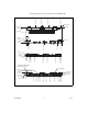
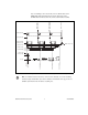
Dimensions This section contains dimensional drawings of the sbRIO devices. For three-dimensional models, go to ni.com/singleboard and look on the Resource tab for the sbRIO device you are using. The plated mounting holes are all connected to P1, the ground lug. Connect P1 or one of the plated mounting holes securely to earth ground.
8.076 (205.13) 5.147 (130.72) 3.691 (93.75) 2.237 (56.81) The following figure shows the dimensions of the sbRIO-960x. 7X Ø .134 (3.4) 3.650 (92.71) 3.520 (89.41) 3.520 (89.41) 2.440 (61.98) .550 (13.97) .275 (6.99) .140 (3.56) .450 (11.43) 8.200 (208.28) 7.295 (185.29) 4.100 (104.14) .810 (20.57) .000 (0) .775 (19.69) .000 (0) .469 (11.91) 7.911 (200.94) 8.200 (208.28) 6.927 (175.95) 5.001 (127.03) 4.017 (102.03) 2.091 (53.11) .940 (23.88) 1.107 (28.12) .000 (0) .286 (7.26) .
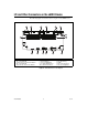
8.709 (221.21) 2.889 (73.38) 2.910 (73.91) 5.799 (147.29) 5.820 (147.83) You can install up to three board-only C Series I/O modules on the sbRIO-960x. The following figure shows the dimensions of the sb-RIO-960x with three board-only C Series I/O modules installed. 6.565 (166.75) 5.515 (140.08) 4.265 (108.33) 3.965 (100.71) 3.650 (92.71) 8X Ø .125 (3.18) 2.885 (73.28) 2.514 (63.86) Ø.512 (13) 1.212 (30.78) 8.200 (208.28) 6.442 (163.63) 3.340 (84.84) .000 (0) .285 (7.23) .000 (0) Figure 3.
I/O and Other Connectors on the sbRIO Device The following figure shows the locations of parts on the sbRIO device. 1 2 3 4 5 6 7 15 8 14 1 2 3 4 5 J11, Connector for C Series Module P5, 3.3 V Digital I/O J10, Connector for C Series Module P4, 3.3 V Digital I/O J9, Connector for C Series Module 13 12 6 7 8 9 10 11 10 DIP Switches Backup Battery P2, 3.3 V Digital I/O J5, RJ-45 Ethernet Port J1, RS-232 Serial Port 9 11 12 13 14 15 Reset Button P1, Ground Lug LEDs J3, Power Connector P3, 3.
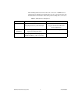
The following table lists and describes the connectors on sbRIO devices and lists the part number and manufacturer of each connector. Refer to the manufacturer for information about using and matching these connectors. Table 1. sbRIO Connector Descriptions Connector Description Part Number and Manufacturer J3, Power 2-position MINI-COMBICON header and plug, 0.285 in. (7.
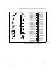
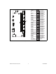
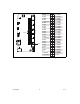
The following figures show the pinouts of the I/O connectors on the sbRIO devices.
Pin 50 D GND 5V 50 49 48 47 Port9/DIO8 D GND 46 45 44 43 42 41 Port9/DIO6 40 39 38 37 Port9/DIO3 36 35 34 33 Port9/DIO1 32 31 Port9/DIO9 Port8/DIO8 D GND 30 29 28 27 26 25 D GND D GND D GND D GND 24 22 20 18 23 21 19 17 Port8/DIO5 D GND D GND Port8/DIOCTL 16 15 14 13 12 11 Port8/DIO1 D GND D GND D GND 10 8 6 4 9 7 5 3 Port7/DIO8 2 1 D GND 5V D GND D GND D GND D GND D GND Port9/DIOCTL Pin 1 D GND D GND D GND Port7/DIO4 Port9/DIO7 Port9/DIO5 Port9/DIO4 Port9/DIO2 Port9/DIO0 P
D GND D GND 50 49 48 47 Port2/DIO3 D GND 46 44 42 40 38 45 43 41 39 37 Port2/DIO1 36 35 34 33 Port1/DIO6 32 31 Port1/DIO4 Port1/DIO3 D GND 30 29 28 27 26 25 D GND Port1/DIOCTL D GND D GND 24 22 20 18 23 21 19 17 Port1/DIO0 D GND D GND D GND 16 15 14 13 12 11 Port0/DIO6 5V D GND 5V 10 8 6 4 9 7 5 3 Port0/DIO3 2 1 D GND D GND Port2/DIOCTL D GND D GND D GND D GND D GND D GND D GND Pin 50 Pin 1 Port0/DIO9 Port0/DIOCTL Port2/DIO2 Port2/DIO0 Port2/DIO9 Port1/DIO8 Port1/DIO7 Port1/DI
Pin 50 D GND 5V 50 49 48 47 Port4/DIO8 D GND 46 45 44 43 42 41 Port4/DIO6 40 39 38 37 Port4/DIO3 36 35 34 33 Port4/DIO1 32 31 Port4/DIO9 Port3/DIO8 D GND 30 29 28 27 26 25 D GND D GND D GND D GND 24 22 20 18 23 21 19 17 Port3/DIO5 D GND D GND Port3/DIOCTL 16 15 14 13 12 11 Port3/DIO1 D GND D GND D GND 10 8 6 4 9 7 5 3 Port7/DIO3 2 1 D GND 5V D GND D GND D GND D GND Pin 1 D GND Port4/DIOCTL D GND D GND Port7/DIO9 Port7/DIOCTL Port4/DIO7 Port4/DIO5 Port4/DIO4 Port4/DIO2 Port4/D
Table 2. RS-232 Serial Port Pin Descriptions Pin Signal 1 DCD 2 RXD 3 TXD 4 DTR 5 GND 6 DSR 7 RTS 8 CTS 9 RI Connecting the sbRIO Device to a Network Use a standard Category 5 (CAT-5) or better Ethernet cable to connect the RJ-45 Ethernet port to an Ethernet network. To prevent data loss and to maintain the integrity of your Ethernet installation, do not use a cable longer than 100 m.
Powering the sbRIO Device The sbRIO device requires a power supply connected to J3. The supply voltage and current must meet the specifications in the Power Requirements section of this document, but the actual power requirement depends on how the device is physically configured, programmed, and used. To determine the power requirement of your application, you must measure the power consumption during execution, and add 20% to your estimates to account for transient and startup conditions.
Boot Options Table 3 lists the reset options available on sbRIO devices. These options determine how the FPGA behaves when the device is reset in various conditions. Table 3. sbRIO Reset Options Reset Option Behavior Do Not Autoload VI Does not load the FPGA bit stream from flash memory. Autoload VI on Device Power-Up Loads the FPGA bit stream from flash memory to the FPGA when the device powers on.
Configuring DIP Switches AMP 0650 1-5435802-7 OFF 1 2 SAFE MODE CONSOLE OUT 3 4 IP RESET NO APP 5 6 USER1 NO FPGA Figure 10. DIP Switches All of the DIP switches are in the OFF (up) position when the sbRIO device is shipped from National Instruments. SAFE MODE Switch The position of the SAFE MODE switch determines whether the embedded LabVIEW Real-Time engine launches at startup. If the switch is in the OFF position, the LabVIEW Real-Time engine launches.
• One stop bit • No flow control Keep this switch in the OFF position during normal operation. If CONSOLE OUT is enabled, LabVIEW RT cannot communicate with the serial port. IP RESET Switch Push the IP RESET switch to the ON position and reboot the sbRIO device to reset the IP address to 0.0.0.0. If the device is on your local subnet and the IP RESET switch is in the ON position, the device appears in MAX with IP address 0.0.0.0. You can configure a new IP address for the device in MAX.
Using the Reset Button Pressing the Reset button reboots the processor. The FPGA continues to run unless you select the Autoload VI on Device Reboot boot option. Refer to the Boot Options section for more information. Understanding LED Indications 1 2 1 3 2 4 FPGA USER 3 4 POWER STATUS Figure 11. sbRIO-960x LEDs FPGA LED You can use the FPGA LED to help debug your application or easily retrieve application status.
Table 4. Status LED Indications Number of Flashes Indication 1 The device is unconfigured. Use MAX to configure the device. Refer to the Measurement & Automation Explorer Help for information about configuring the device. 2 The device has detected an error in its software. This usually occurs when an attempt to upgrade the software is interrupted. Reinstall software on the device. Refer to the Measurement & Automation Explorer Help for information about installing software on the device.
The network settings are restored. You can reconfigure the settings in MAX from a computer on the same subnet. Refer to the Measurement & Automation Explorer Help for more information about configuring the device. Note If the device is restored to the factory network settings, the LabVIEW run-time engine does not load. You must reconfigure the network settings and reboot the device for the LabVIEW run-time engine to load. Integrated 3.
During overvoltage conditions, high current flows through R1 and into the protection diodes. High current causes internal heating in the posistor, which increases the resistance and limits the current. Refer to the Specifications section for current-limiting and resistance values. Drive Strength The sbRIO devices were tested with all 110 DIO channels driving 3 mA DC loads, for a total of 330 mA sourcing from the FPGA.
The OEM user is responsible for determining cabling requirements and ensuring that current limits are not exceeded. Specifications The following specifications are typical for the range –20 to 55 °C unless otherwise noted. Network Network interface................................... 10BaseT and 100BaseTX Ethernet Compatibility ......................................... IEEE 802.3 Communication rates ............................. 10 Mbps, 100 Mbps, auto-negotiated Maximum cabling distance ..................
3.3 V Digital I/O Number of DIO channels........................110 Maximum tested current per channel .....3 mA Maximum total current, all lines.............330 mA Maximum tested DIO frequency ............10 MHz Input logic levels Input high voltage, VIH ....................2.0 V min; 5.25 V max Input low voltage, VIL ......................0 V min; 0.8 V max Output logic levels Output high voltage, VOH , sourcing 3 mA .................................2.7 V min; 3.
Resistance-temperature characteristics, typical curve Resistance-Temperature Characteristics Typical Curve Graph-1 0 140 1000 Resistance Change (R/R25) 100 10 1 0.
Power Requirements The sbRIO device requires a power supply connected to connector J3. Refer to Figure 4 for the location of J3. Refer to the Powering the sbRIO Device section for information about connecting the power supply. Power supply voltage range....................19–30 VDC1 Power supply current limit .....................1.8 A Power connector internal fuse ................
Example power requirement calculations For an sbRIO-9602 with three installed board-only C Series modules, 20 mA total current through 3.3 V DIO pins, and 1 A of current through 5 V output, calculate the total power requirement as follows: Pint = 6.0 W PCSer = 3.30 W PDIO = 0.08 W P5V = 5.55 W Adding 20% for transient conditions, 14.93 W × 1.2 = 17.92 W Total power requirement = 17.92 W For an sbRIO-9601 with one installed board-only C Series module, 330 mA total current through 3.
For additional environmental information, refer to the NI and the Environment Web page at ni.com/environment. This page contains the environmental regulations and directives with which NI complies, as well as other environmental information not included in this document. Waste Electrical and Electronic Equipment (WEEE) At the end of their life cycle, all products must be sent to a WEEE recycling center. For more information about WEEE recycling centers and National Instruments WEEE initiatives, visit ni.
Cabling Table 5 shows the standard Ethernet cable wiring connections for both normal and crossover cables. Table 5.
Where to Go for Support The National Instruments Web site is your complete resource for technical support. At ni.com/support you have access to everything from troubleshooting and application development self-help resources to email and phone assistance from NI Application Engineers. National Instruments corporate headquarters is located at 11500 North Mopac Expressway, Austin, Texas, 78759-3504. National Instruments also has offices located around the world to help address your support needs.