USER GUIDE AND SPECIFICATIONS NI USB-6008/6009 This user guide describes how to use the National Instruments USB-6008/6009 data acquisition (DAQ) devices and lists specifications. Introduction The NI USB-6008/6009 provides connection to eight analog input (AI) channels, two analog output (AO) channels, 12 digital input/output (DIO) channels, and a 32-bit counter with a Full-Speed USB interface. This manual revision updates naming conventions to reflect the conventions used in NI-DAQmx.
Table 2. Differences Between the NI USB-6008 and NI USB-6009 Feature NI USB-6008 NI USB-6009 12 bits differential, 11 bits single-ended 14 bits differential, 13 bits single-ended Maximum AI Sample Rate, Single Channel* 10 kS/s 48 kS/s Maximum AI Sample Rate, Multiple Channels (Aggregate)* 10 kS/s 48 kS/s Open collector Open collector or active drive AI Resolution DIO Configuration * System dependent.
Dimensions Figure 3 illustrates the dimensions of the NI USB-6008/6009 device. 23.19 mm (0.913 in.) 81.81 mm (3.221 in.) 85.09 mm (3.350 in.) NATIONAL INSTRUMENTS 76.09 mm (2.996 in.) 63.50 mm (2.500 in.) 72.65 mm (2.860 in.) Figure 3. NI USB-6008/6009 in Millimeters (Inches) Safety Guidelines Caution Operate the NI USB-6008/6009 only as described in these operating instructions.
Do not operate the device in an explosive atmosphere or where there may be flammable gases or fumes. If you must operate the device in such an environment, it must be in a suitably rated enclosure. If you need to clean the device, use a dry cloth. Make sure that the device is completely dry and free from contaminants before returning it to service. Operate the device only at or below Pollution Degree 2.
• Measurement Category II is for measurements performed on circuits directly connected to the electrical distribution system. This category refers to local-level electrical distribution, such as that provided by a standard wall outlet (for example, 115 V for U.S. or 230 V for Europe). Examples of Measurement Category II are measurements performed on household appliances, portable tools, and similar E Series devices.
LabVIEW If you are a new user, use the Getting Started with LabVIEW manual to familiarize yourself with the LabVIEW graphical programming environment and the basic LabVIEW features you use to build data acquisition and instrument control applications. Open the Getting Started with LabVIEW manual by selecting Start»All Programs»National Instruments»LabVIEW»LabVIEW Manuals or by navigating to the labview\manuals directory and opening LV_Getting_Started.pdf.
based on your task or channel in Measurement Studio. Refer to the DAQ Assistant Help for additional information about generating code. You also can create channels and tasks, and write your own applications in your ADE using the NI-DAQmx API. For help with NI-DAQmx methods and properties, refer to the NI-DAQmx .NET Class Library or the NI-DAQmx Visual C++ Class Library included in the NI Measurement Studio Help.
Library»Reference to view the function reference. Expand NI Measurement Studio Help»NI Measurement Studio .NET Class Library»Using the Measurement Studio .NET Class Libraries to view conceptual topics for using NI-DAQmx with Visual C# and Visual Basic .NET. To get to the same help topics from within Visual Studio, go to Help»Contents. Select Measurement Studio from the Filtered By drop-down list and follow the previous instructions.
Note All NI-DAQmx Base documentation for Linux is installed at /usr/local/natinst/nidaqmxbase/documentation. Note All NI-DAQmx Base documentation for Mac OS X is installed at /Applications/National Instruments/NI-DAQmx Base/documentation. Training Courses If you need more help getting started developing an application with NI products, NI offers training courses. To enroll in a course or obtain a detailed course outline, refer to ni.com/training.
Note For information about non-Windows operating system support, refer to ni.com/ info and enter BaseGSGML. Installing the NI USB-6008/6009 Device Before installing the device, you must install the software you plan to use with the device. Refer to the Installing the Software section of this guide and the documentation included with the software for more information. External Power Supply Vbus +5 V/200 mA PFI 0 USB USB Microcontroller P1.<0..3> P0.<0..
Setting Up the NI USB-6008/6009 Device Complete the following steps to set up the NI USB-6008/6009: 1. Install combicon screw terminal blocks by inserting them into the combicon jacks. 2. Figure 5 illustrates the signal labels that ship in the NI USB-6008/6009 kit. You can apply the signal labels to the screw terminal blocks for easy signal identification.
4 3 2 3 2 bi t, N M IU ul S tif B un ct 60 io 0 n 9 I/O ig D l a it 7 1 1 1 8 In p ut s, 14 - 2 A a n 3 lo g 6 1 1 2 Overlay Label with Pin Orientation Guides Combicon Jack 3 4 Signal Labels USB Cable Figure 6. Signal Label Application Diagram Once you label the screw terminal blocks, you must only insert them into the matching combicon jack, as indicated by the overlay label on the NI USB-6008/6009 device. Note 4. Connect the wiring to the appropriate screw terminals.
Connecting the NI USB-6008/6009 to a Computer Plug one end of the USB cable into the NI USB-6008/6009 and the other end into an available USB port on the computer. LED Indicator The NI USB-6008/6009 device has a green LED next to the USB connector. The LED indicator indicates device status, as listed in Table 3. When the device is connected to a USB port, the LED blinks steadily to indicate that the device is initialized and is receiving power from the connection.
I/O Connector The NI USB-6008/6009 ships with one detachable screw terminal block for analog signals and one detachable screw terminal block for digital signals. These terminal blocks provide 16 connections that use 16 AWG to 28 AWG wire. Table 4 lists the analog terminal assignments, and Table 5 lists the digital terminal assignments. Table 4.
Table 5. Digital Terminal Assignments 32 31 30 29 28 27 26 25 24 23 22 21 20 19 18 17 Module © National Instruments Corporation 15 Terminal Signal 17 P0.0 18 P0.1 19 P0.2 20 P0.3 21 P0.4 22 P0.5 23 P0 6 24 P0.7 25 P1.0 26 P1.1 27 P1.2 28 P1.3 29 PFI 0 30 +2.
Signal Descriptions Table 6 describes the signals available on the I/O connectors. Table 6. Signal Descriptions Signal Name Reference Direction Description — — Ground—The reference point for the single-ended AI measurements, bias current return point for differential mode measurements, AO voltages, digital signals at the I/O connector, +5 VDC supply, and the +2.5 VDC reference. GND AI <0..
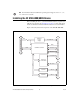
Analog Input You can connect analog input signals to the NI USB-6008/6009 through the I/O connector. Refer to Table 6 for more information about connecting analog input signals. Analog Input Circuitry Figure 7 illustrates the analog input circuitry of the NI USB-6008/6009. +2.5 VREF 30.9 kΩ MUX ADC PGA AI FIFO 127 kΩ AI 39.2 kΩ Input Range Selection Figure 7. Analog Input Circuitry MUX The NI USB-6008/6009 has one analog-to-digital converter (ADC).
AI FIFO The NI USB-6008/6009 can perform both single and multiple A/D conversions of a fixed or infinite number of samples. A first-in-first-out (FIFO) buffer holds data during AI acquisitions to ensure that no data is lost. Analog Input Modes You can configure the AI channels on the NI USB-6008/6009 to take single-ended or differential measurements. Refer to Table 6 for more information about I/O connections for single-ended or differential measurements.
20 15 Amplitude (V) 10 5 AI 1 AI 5 Result 0 –5 –10 –15 –20 Figure 9. Example of a Differential 20 V Measurement Connecting a signal greater than ±10 V on either pin results in a clipped output. 20 15 Amplitude (V) 10 5 AI 1 AI 5 Result 0 –5 –10 –15 –20 Figure 10.
AI Voltage Source NI USB-6008/6009 GND Figure 11. Connecting a Reference Single-Ended Voltage Signal Digital Trigger When an AI task is defined, you can configure PFI 0 as a digital trigger input. When the digital trigger is enabled, the AI task waits for a rising or falling edge on PFI 0 before starting the acquisition. To use ai/Start Trigger with a digital source, specify PFI 0 as the source and select rising or falling edge.
DACs Digital-to-analog converts (DACs) convert digital codes to analog voltages. Connecting Analog Output Loads To connect loads to the NI USB-6008/6009, connect the positive lead of the load to the AO terminal, and connect the ground of the load to a GND terminal. AO Load NI USB-6008/6009 GND Figure 13. Connecting a Load Minimizing Glitches on the Output Signal When you use a DAC to generate a waveform, you may observe glitches in the output signal.
Digital I/O Circuitry Figure 14 shows P0.<0..7> connected to example signals configured as digital inputs and digital outputs. You can configure P1.<0..3> similarly. +5 V 1 LED P0.0 P0.1 P0.2 P0.3 P0.4 P0.5 P0.6 P0.7 LED 2 3 +5 V TTL Signal 4 Switch GND I/O Connector 1 2 3 4 P0.0 configured as an open collector digital output driving a LED P0.2 configured as a active drive digital output driving a LED P0.4 configured as a digital input receiving a TTL signal from a gated invertor P0.
NI USB-6008/6009 +5 V +5 V Re Rp 4.7 KΩ Onboard Resistor External Pull-Up Resistor Port Pad P0.0 Rl Load A GND Figure 15. Example of Connecting an External User-Provided Resistor Complete the following steps to determine the value of the user-provided pull-up resistor: 1. Place an ammeter in series with the load. 2. Place a variable resistor between the digital output line and the +5 V. 3. Adjust the variable resistor until the ammeter current reads as the intended current.
I/O Protection To protect the NI USB-6008/6009 against overvoltage, undervoltage, and overcurrent conditions, as well as ESD events, you should avoid these fault conditions by using the following guidelines: • If you configure a DIO line as an output, do not connect it to any external signal source, ground signal, or power supply. • If you configure a DIO line as an output, understand the current requirements of the load connected to these signals.
Reference and Power Sources The NI USB-6008/6009 creates an external reference and supplies a power source. All voltages are relative to COM unless otherwise noted. +2.5 External References The NI USB-6008/6009 creates a high-purity reference voltage supply for the ADC using a multi-state regulator, amplifier, and filter circuit. The resulting +2.5 V reference voltage can be used as a signal for self test. +5 V Power Source The NI USB-6008/6009 supplies a 5 V, 200 mA output.
Timing accuracy .....................................100 ppm of actual sample rate Input range Single-ended ....................................±10 V Differential ......................................±20 V1, ±10 V, ±5 V, ±4 V, ±2.5 V, ±2 V, ±1.25 V, ±1 V Working voltage .....................................±10 V Input impedance .....................................144 kΩ Overvoltage protection ...........................±35 Trigger source.........................................
Range Typical at 25 °C (mV) Maximum over Temperature (mV) ±2 2.21 42.5 ±1.25 1.70 38.9 ±1 1.53 37.5 Analog Output Analog outputs ....................................... 2 Output resolution.................................... 12 bits Maximum update rate ............................ 150 Hz, software-timed Output range........................................... 0 to +5 V Output impedance .................................. 50 Ω Output current drive ...............................
Compatibility ..........................................TTL, LVTTL, CMOS Absolute maximum voltage range ..........–0.5 to 5.8 V with respect to GND Pull-up resistor........................................4.7 kΩ to 5 V Power-on state ........................................Input Digital logic levels Level Input low voltage Input high voltage Input leakage current Output low voltage (I = 8.5 mA) Output high voltage Active drive (push-pull), I = –8.5 mA Open collector (open-drain), I = –0.
Minimum low pulse width ..................... 100 ns Input high voltage .................................. 2.0 V Input low voltage ................................... 0.8 V Bus Interface USB specification .................................. USB 2.0 Full-Speed USB bus speed ....................................... 12 Mb/s Power Requirements USB 4.10 to 5.25 VDC ............................ 80 mA typical, 500 mA max USB suspend...................................
Safety If you need to clean the module, wipe it with a dry towel. Safety Voltages Connect only voltages that are within these limits. Channel-to-GND ....................................±30 V max, Measurement Category I Measurement Category I is for measurements performed on circuits not directly connected to the electrical distribution system referred to as MAINS voltage. MAINS is a hazardous live electrical supply system that powers equipment.
Maximum altitude .................................. 2,000 m (at 25 °C ambient temperature) Storage temperature (IEC 60068-2-1 and IEC 60068-2-2) ..... –40 to 85 °C Storage humidity (IEC 60068-2-56) .................................. 5 to 90% RH, noncondensing Pollution Degree (IEC 60664) ...............
Waste Electrical and Electronic Equipment (WEEE) At the end of their life cycle, all products must be sent to a WEEE recycling center. For more information about WEEE recycling centers and National Instruments WEEE initiatives, visit ni.com/environment/weee.htm. EU Customers ⬉ᄤֵᙃѻક∵ᶧࠊㅵ⧚ࡲ⊩ ˄Ё RoHS˅ Ёᅶ᠋ National Instruments ヺড়Ё⬉ᄤֵᙃѻકЁ䰤ࠊՓ⫼ᶤѯ᳝ᆇ⠽䋼ᣛҸ (RoHS)DŽ ݇Ѣ National Instruments Ё RoHS ড়㾘ᗻֵᙃˈ䇋ⱏᔩ ni.com/environment/rohs_chinaDŽ (For information about China RoHS compliance, go to ni.