
User's Manual

Chapter 2 Hardware Overview
NI PCI-1426 User Manual 2-2 ni.com
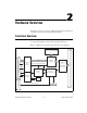
Camera Link and the NI 1426
The NI 1426 supports the Camera Link Base configuration.
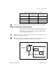
Base Configuration
The Camera Link Base configuration places 24 data bits and four enable
signals (Frame Valid, Line Valid, Data Valid, and a spare) on a single
Channel Link part and cable.
The Base configuration includes asynchronous serial transmission as well
as four digital camera control lines for controlling exposure time, frame
rates, and other camera control signals. These four control lines are
configured in the camera file to generate precise timing signals for
controlling digital camera acquisition.
Base configuration includes the following bit allocations:
•8-bit × 1, 2, and 3 taps (channels)
• 10-bit × 1 and 2 taps
• 12-bit × 1 and 2 taps
• 14-bit × 1 tap
• 16-bit × 1 tap
• 24-bit RGB
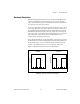
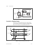
Data Transmission
A 28-to-4 serializing Channel Link chip drives the data and camera enable
signals across the Camera Link cable, and the camera’s pixel clock controls
the Channel Link’s data transmission. The four LVDS pairs are then
deserialized by another Channel Link chip on the NI 1426.
Note Exact timing of camera and image acquisition device communication is camera
dependent. Refer to the Specifications of the Camera Link Interface Standard for Digital
Cameras and Frame Grabbers manual for more information about Camera Link timing
requirements.