
User's Manual

Chapter 3 Signal Connections
NI PCI-1426 User Manual 3-4 ni.com
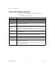
Connector Signal Connection Descriptions
Table 3-1 describes the MDR 26-pin and 15-pin D-SUB signal
connections.
Table 3-1. I/O Connector Signals
Signal Name Description
TTL_TRIG<3..0> TTL external triggers/DIO lines (I/O).
DGND Direct connection to digital GND on the NI 1426.
ISO_IN<1..0>± 30 V isolated input only lines.
Use these lines instead of, not in addition to, TTL_TRIG<1..0>.
PHASE_A±
PHASE_B±
The primary use of these signals is for interfacing to a quadrature encoder.
Alternatively, these pairs can be used as independent RS-422 trigger inputs
instead of, not in addition to, TTL_TRIG<3..2>.
X<3..0>± LVDS Base configuration data and enable signals from the camera to the
acquisition device.
XCLK± Transmission clock on the Base configuration chip for Camera Link
communication between the acquisition device and the camera.
SerTC± Serial transmission to the camera from the image acquisition device.
SerTFG± Serial transmission to the frame grabber from the camera.
CC<4..1>± Four LVDS pairs, defined as camera inputs and acquisition device outputs,
reserved for camera control.
On some cameras, the camera controls allow the acquisition device to control
exposure time and frame rate.