SC-2043-SG User Manual Eight-Channel Strain Gauge Signal Conditioning Accessory August 1996 Edition Part Number 320995B-01 © Copyright 1995, 1996 National Instruments Corporation. All Rights Reserved.
National Instruments Corporate Headquarters 6504 Bridge Point Parkway Austin, TX 78730-5039 (512) 794-0100 Technical support fax: (800) 328-2203 (512) 794-5678 Branch Offices: Australia 03 9 879 9422, Austria 0662 45 79 90 0, Belgium 02 757 00 20, Canada (Ontario) 519 622 9310, Canada (Québec) 514 694 8521, Denmark 45 76 26 00, Finland 90 527 2321, France 1 48 14 24 24, Germany 089 741 31 30, Hong Kong 2645 3186, Italy 02 48301892, Japan 03 5472 2970, Korea 02 596 7456, Mexico 95 800 010 0793, Netherlands 0
Limited Warranty The SC-2043-SG is warranted against defects in materials and workmanship for a period of one year from the date of shipment, as evidenced by receipts or other documentation. National Instruments will, at its option, repair or replace equipment that proves to be defective during the warranty period. This warranty includes parts and labor.
WARNING REGARDING MEDICAL AND CLINICAL USE OF NATIONAL INSTRUMENTS PRODUCTS National Instruments products are not designed with components and testing intended to ensure a level of reliability suitable for use in treatment and diagnosis of humans. Applications of National Instruments products involving medical or clinical treatment can create a potential for accidental injury caused by product failure, or by errors on the part of the user or application designer.
Contents About This Manual ...............................................................................................................ix Organization of This Manual ............................................................................................ix Conventions Used in This Manual ....................................................................................x National Instruments Documentation ...............................................................................
Contents Chapter 4 Theory of Operation ..........................................................................................................4-1 Functional Overview ......................................................................................................4-1 Bridge Completion Network ..........................................................................................4-3 Amplification ......................................................................................................
Contents Figures Figure 1-1. The Relationship between the Programming Environment, NI-DAQ, and Your Hardware .............................................................................1-3 Figure 2-1. SC-2043-SG Parts Locator Diagram ...................................................................2-2 Figure 3-1. Figure 3-2. Figure 3-3. Full-Bridge Connection to the SC-2043-SG........................................................3-8 Half-Bridge Connection to the SC-2043-SG .......................
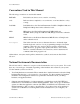
About This Manual This manual describes the electrical and mechanical aspects of the SC-2043-SG and contains information concerning its configuration and operation. The SC-2043-SG is an eight-channel strain gauge signal conditioning accessory for National Instruments DAQ boards. The conditioned strain gauge signals are routed directly to the analog input channels of the DAQ board via a 50-pin connector.
About This Manual Conventions Used in This Manual The following conventions are used in this manual: bold italic Bold, italic text denotes a note, caution, or warning. italic Italic text denotes emphasis, a cross reference, or an introduction to a key concept. Lab/1200 Lab/1200 refers to the National Instruments Lab-PC+, DAQPad-1200, and DAQCard-1200 products unless otherwise noted.
About This Manual • Accessory manuals–If you are using accessory products, read the terminal block and cable assembly installation guides or accessory board user manuals. They explain how to physically connect the relevant pieces of the system together. Consult these guides when you are making your connections.
Chapter 1 Introduction This chapter describes the SC-2043-SG, lists what you need to get started with your SC-2043-SG, describes the optional software and optional equipment, and explains how to unpack your SC-2043-SG. About the SC-2043-SG The SC-2043-SG is an eight-channel signal conditioning board that interfaces strain gauge signals to National Instruments DAQ boards.
Introduction Chapter 1 One of the following: SH6850 cable or R6850 cable assembly kit (MIO E Series DAQ board) NB-1 cable (MIO Series, Lab-PC+, or DAQPad-1200 board) PR50-50F cable (DAQCard-1200) Detailed specifications of the SC-2043-SG are in Appendix A, Specifications. Software Programming Choices There are several options to choose from when programming your National Instruments DAQ and SCXI hardware. You can use LabVIEW, LabWindows/CVI, NI-DAQ, or register-level programming.
Chapter 1 Introduction minimal modifications to your code. Figure 1-1 illustrates the relationship between NI-DAQ and LabVIEW and LabWindows/CVI. Conventional Programming Environment (PC, Macintosh, or Sun SPARCstation) LabVIEW (PC, Macintosh, or Sun SPARCstation) LabWindows/CVI (PC or Sun SPARCstation) NI-DAQ Driver Software Personal Computer or Workstation DAQ or SCXI Hardware Figure 1-1.
Introduction Chapter 1 Unpacking Your SC-2043-SG board is shipped in an antistatic package to prevent electrostatic damage to the board. Electrostatic discharge can damage several components on the board. To avoid such damage in handling the board, take the following precautions: • Ground yourself via a grounding strap or by holding a grounded chassis such as a computer chassis. • Touch the antistatic package to a metal part of your computer chassis before removing the board from the package.
Chapter 2 Installation and Configuration This chapter describes the installation and configuration of your SC-2043-SG. The topics discussed are connection of the SC-2043-SG to the DAQ board and switch and jumper configuration for your SC-2043-SG. Installation Note: You must power off your computer—and the SC-2043-SG if externally powered— before installing or making any connection to the SC-2043-SG. The SC-2043-SG includes two 50-pin cable connectors for signal connection to a DAQ board.
Installation and Configuration Chapter 2 The SC-2043-SG has one slide switch and 12 jumpers that you use to configure your board. Figure 2-1 shows the switch and jumpers in the parts locator diagram.
Chapter 2 Installation and Configuration Switch SW1 selects the power supply source for the SC-2043-SG board. Two jumpers, W1 and W3, select the excitation source for the strain gauge bridges. Jumper W2 routes either the excitation voltage signal or the channel 0 signal to analog input channel 0 on the DAQ board. Jumper W8 routes either the excitation voltage signal or an external signal to analog input channel 8 (for MIO and MIO E Series boards only).
Installation and Configuration Chapter 2 Onboard/External Excitation Selection If you want to use the onboard voltage excitation source to excite your strain gauge bridges, set both jumpers W1 and W3 to the INT position. If you want to use an external excitation source, set both jumpers W1 and W3 to the EXT position and connect your excitation source to connector J7. Table 2-3.
Chapter 2 Installation and Configuration Local Excitation Sense Selection MIO or MIO E Series Boards If you are using the SC-2043-SG with an MIO or MIO E Series board, you can locally sense the exact level of the excitation voltage by routing the excitation voltage (internal or external) to one of two analog channels, selected by jumpers W8 and W2. Table 2-4 shows these jumper settings. Setting jumper W8 to the EX position (the factory setting) routes the excitation voltage to ACH8 so you can use ACH<0..
Installation and Configuration Chapter 2 Lab/1200 Series Boards If you are using the SC-2043-SG with a Lab/1200 Series board, you can locally sense the exact level of the excitation voltage by routing the excitation voltage (internal or external) to ACH0, configured by jumper W2. The SC-2043-SG also has jumper W8, which you must also configure. Table 2-5 shows these jumper settings.
Chapter 2 Installation and Configuration Bridge Completion Selection Jumpers W4–W7 and W10–W13 select half-bridge or full-bridge configuration for each channel on the SC-2043-SG. Setting a jumper in the FB position disconnects the half-bridge completion network from the channel and connects the CHn- screw terminal to the negative input of the instrumentation amplifier for full-bridge signal inputs.
Installation and Configuration Chapter 2 Additionally, there are sockets for eight quarter-bridge completion resistors. When inserted, the quarter-bridge completion resistors connect to the positive inputs of the instrumentation amplifiers and the -EXn terminals. To configure a channel for quarter-bridge completion, set the corresponding bridge completion jumper to the HB position and insert your quarter-bridge completion resistor into the appropriate sockets.
Chapter 3 Signal Connections This chapter describes the signal connections to the SC-2043-SG board. I/O Connector Pin Description Warning: Connections, including any power signals connected to ground and vice versa, that exceed any of the maximum input or output signal ratings on the SC-2043-SG and the DAQ board can damage the SC-2043-SG, the DAQ board, and the computer. National Instruments is NOT liable for any damages resulting from any such signal connections.
Signal Connections Chapter 3 Table 3-1.
Chapter 3 Signal Connections Table 3-1. Pin Assignments for the MIO I/O Connectors (Continued) Pin Numbers 38 39 40 41 42 43 44 45 46 47 48 49 50 MIO Connector Signal MIO E Series I/O Connector Names Signal Names †† TRIG1 †† TRIG2 EXTCONV* CONVERT* SOURCE1 GPCTR1_SOURCE GATE1 GPCTR1_GATE OUT1 GPCTR1_OUT †† UPDATE* GATE2 WFTRIG OUT2 STARTSCAN SOURCE5 GPCTR0_SOURCE GATE5 GPCTR0_GATE OUT5 GPCTR0_OUT FOUT FREQ_OUT † These signals are not routed to screw terminals.
Signal Connections Chapter 3 Table 3-2.
Chapter 3 Signal Connections Table 3-2. Pin Assignments for the Lab/1200 I/O Connector (Continued) Pin Numbers 38 39 40 41 42 43 44 45 46 47 48 49 50 † Lab/1200 Connector Signal Names EXTTRIG EXTUPDATE* EXTCONV* OUTB0 GATB0 OUTB1 GATB1 CLKB1 OUTB2 GATB2 CLKB2 +5 V† DGND† These signals are not routed to screw terminals. All other signals on the I/O connectors are routed directly to screw terminals (J1–J6) for convenient signal termination. Table 3-3.
Signal Connections Chapter 3 Table 3-4. Lab/1200 (J9) I/O Connector Signal Summary Signal Name Pin Number Description AGND 11 Analog Ground—This pin provides the AC noise current return point for the analog circuitry and for the onboard excitation supply. It is also routed to a screw terminal. AISENSE 9 Analog Input Sense—This pin is the reference node for the conditioned strain gauge bridge signals. It is also routed to a screw terminal.
Chapter 3 Signal Connections Table 3-5 lists the screw terminals (J1–J6) signal summary. Table 3-5. Screw Terminals J1–J6 Signal Summary Signal Name Description CH<0..7>± Input Channels—These inputs are the input signals for analog channels 0 through 7. ±EX<0..7> Voltage Excitation Outputs—These output signals route the excitation voltage supply (internal or external) to the sensors connected to these channels.
Signal Connections Chapter 3 Full-Bridge Connection In this configuration all four elements of the bridge are external to the SC-2043-SG. Four lead wires connect the full-bridge to screw terminals +EXn, -EXn, CHn+, and CHn-. The pair of wires connected to +EXn and -EXn provides excitation voltage to the bridge, and the other pair connected to CHn+ and CHn- senses the output voltage of the bridge. Figure 3-1 shows this configuration, along with the appropriate half-bridge jumper placement.
Chapter 3 Signal Connections Quarter-Bridge Connection In this configuration only one strain gauge is used. Bridge completion is provided by the internal half-bridge completion reference as well as a quarter-bridge completion resistor. This quarterbridge completion resistor is equal in value to the external strain gauge element. Insert your completion resistor in the appropriate sockets. Two lead wires connect the quarter-bridge strain gauge to screw terminals +EXn and CHn+.
Signal Connections Chapter 3 To null the static voltage offset of the system, including the bridge, use the following procedure: 1. Configure and connect your bridge to the selected channel. 2. Read the channel output. 3. While monitoring the output, rotate the trimming potentiometer wiper with a flathead screwdriver until you reach 0 V. You have nulled your system offset and are ready for a measurement.
Chapter 3 Signal Connections For example, assuming: EX = 2.5 V Vdesired nulling range RTI = ±1 mV RTI Then, using the above formula, the new nulling resistor should have a value of: 100 R null ≈ 2.
Chapter 4 Theory of Operation This chapter contains a functional overview of the SC-2043-SG board and explains the operation of each functional unit making up the SC-2043-SG. Functional Overview The SC-2043-SG consists of eight channels, each comprising a bridge completion network, an instrumentation amplifier with a gain of 10, offset nulling, filtering, and screw terminal connections to accommodate strain gauge bridge measurements.
Theory of Operation Chapter 4 The block diagram in Figure 4-1 illustrates the key functional components of the SC-2043-SG. External Excitation + - Onboard/External Excitation Jumpers External Power +5 V Gnd Internal +2.
Chapter 4 Theory of Operation Bridge Completion Network The SC-2043-SG provides onboard bridge completion that you can use with half-bridge and quarter-bridge networks. The SC-2043-SG has a single half-bridge reference that is common to all channels, consisting of a resistive divider network of two 2.5 kΩ resistors, with 0.02% ratio tolerance and 2 ppm/°C tracking temperature coefficient (TCR). Each channel has a jumper that configures the channel for either half-bridge or full-bridge inputs.
Theory of Operation Chapter 4 Filtering Each channel of the SC-2043-SG has a postgain, lowpass filter. This filter is a single-pole, buffered, RC filter with a cutoff frequency of 1.6 kHz. I/O Connectors and Breakout Screw Terminals The outputs of all eight channels are connected to the ACH<0..7> analog input channel pins on the MIO I/O connector and the Lab/1200 I/O connector. All the remaining pins, except two, on these connectors are mapped to breakout screw terminals (J1–J6).
Chapter 5 Calibration Procedures This chapter discusses the calibration procedures for the SC-2043-SG board. Excitation Adjustment Onboard Excitation Source The excitation voltage source on the SC-2043-SG is factory-adjusted to 2.5 V ±0.5%. This circuit has one potentiometer (R2) that you must adjust to change the excitation voltage level on all eight output channels.
Calibration Procedures Chapter 5 External Excitation Source You can connect an external excitation source of up to 10 VDC to screw terminal block J7 on the SC-2043-SG. If you are using an external excitation source, you must perform the following steps. 1. If you are using a rack-mount kit, remove the cover. Caution: If you are using the SC-2043-SG with a Lab/1200 board, you MUST set jumper W8 to the ST position. Failure to do so can damage your Lab/1200 board if your excitation voltage exceeds 10 V.
Appendix A Specifications This appendix lists the specifications for the SC-2043-SG. These are typical at 25° C unless otherwise noted. Analog Input Input Characteristics Number of channels .................................................... 8 differential Input signal ranges ...................................................... ±1 V (fixed gain of 10 on each channel) Max working voltage (signal + common mode) ......... Each input should remain within ±11 V of ground Overvoltage protection ..............
Specifications Appendix A Bridge type .................................................................. Half or full (jumper-selectable); with sockets for quarterbridge completion Bridge completion ....................................................... Two 2.5 kΩ, ±0.02% ratio tolerance (±2 ppm/°C tracking TCR resistors) Offset nulling range .................................................... ±5 mV, referred to input Power Requirement (from DAQ Board)2 +5 VDC (±10 %) Using external excitation ........
Appendix B Customer Communication For your convenience, this appendix contains forms to help you gather the information necessary to help us solve technical problems you might have as well as a form you can use to comment on the product documentation. Filling out a copy of the Technical Support Form before contacting National Instruments helps us help you better and faster. National Instruments provides comprehensive technical assistance around the world. In the U.S.
Technical Support Form Photocopy this form and update it each time you make changes to your software or hardware, and use the completed copy of this form as a reference for your current configuration. Completing this form accurately before contacting National Instruments for technical support helps our applications engineers answer your questions more efficiently.
SC-2043-SG Hardware and Software Configuration Form Record the settings and revisions of your hardware and software on the line to the right of each item. Complete a new copy of this form each time you revise your software or hardware configuration, and use this form as a reference for your current configuration. Completing this form accurately before contacting National Instruments for technical support helps our applications engineers answer your questions more efficiently.
Documentation Comment Form National Instruments encourages you to comment on the documentation supplied with our products. This information helps us provide quality products to meet your needs. Title: SC-2043-SG User Manual Edition Date: August 1996 Part Number: 320995B-01 Please comment on the completeness, clarity, and organization of the manual. If you find errors in the manual, please record the page numbers and describe the errors. Thank you for your help.
Glossary ___________________________________________________ ˚ Ω +5 V A ACH# A/D AGND AIGND AISENSE AOGND C CHn± DAC DAC#OUT DAQ DC DGND DIO ±EX ±EXn EXT EXTREF EXTSTROBE* FB HB Hz in.
Glossary NRSE ppm RAM RC rms RTI s SCANCLK ST TCR tempco V VI VDC Vrms SC-2043-SG User Manual nonreferenced single-ended parts per million random-access memory resistance-capacitance root mean square referred to input seconds scan clock signal screw terminal temperature coefficient temperature coefficient volts virtual instrument volts direct current volts, root mean square G-2 © National Instruments Corporation
Index Numbers/Symbols B +5 V signal Lab/1200 (J9) connector summary (table), 3-6 MIO (J10) connector summary (table), 3-5 power supply, 4-4 fuses, 4-4 block diagram of SC-2043-SG, 4-2 board configuration. See configuration.
Index D J DGND signal MIO (J10) connector summary (table), 3-5 Lab/1200 (J9) connector summary (table), 3-6 documentation conventions used in manual, x National Instruments documentation, x organization of manual, ix related documentation, xi J9 (Lab/1200) and J10 (MIO) connectors. See connectors Lab/1200 (J9) and (J10). jumpers and switches. See configuration.
Index register-level programming, 1-3 specifications analog input amplifier characteristics, A-1 dynamic characteristics, A-1 input characteristics, A-1 stability, A-1 transfer characteristics, A-1 environment, A-2 physical, A-2 power requirements, A-2 S SC-2043-SG block diagram, 4-2 features, 1-1 I/O connectors (J9 and J10) (tables), 3-2, 3-4 optional equipment, 1-3 screw terminal (J1–J6) description, 3-6 table, 3-7 software programming choices LabVIEW and LabWindows/CVI application software, 1-2 NI-DAQ