
Barcode Reader User Manual

Chapter 2 Installation and Configuration
© National Instruments Corporation 2-3 SC-2043-SG User Manual
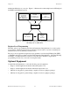
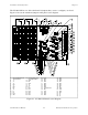
Switch SW1 selects the power supply source for the SC-2043-SG board. Two jumpers, W1 and
W3, select the excitation source for the strain gauge bridges. Jumper W2 routes either the
excitation voltage signal or the channel 0 signal to analog input channel 0 on the DAQ board.
Jumper W8 routes either the excitation voltage signal or an external signal to analog input
channel 8 (for MIO and MIO E Series boards only). Jumpers W4–W7 and W10–W13 configure
the onboard bridge completion network for each of the eight channels for either half-bridge or
full-bridge inputs. Tables 2-2 through 2-6 show the settings for the switch and jumpers.
Power Supply Selection
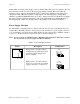
Set switch SW1 to the INT position to draw power from the +5 V line on the DAQ board. Set
switch SW1 to the EXT position to draw power from an external +5 V power supply connected
to J8. In external power mode, the SC-2043-SG has two fuses, F1 and F2, to limit the current to
1 A at +5 V. The board also has a spare fuse (F3), as shown in Figure 2-1.
Note: If you are using an NB-MIO-16X or a DAQPad-1200 with the SC-2043-SG, you must
use an external +5 V power supply with the SC-2043-SG.
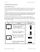
Table 2-2. Power Supply Selection
Switch Description Configuration
SW1J8
INT position—Use this setting to
configure the SC-2043-SG to draw
power through the DAQ board.
(factory setting)
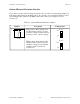
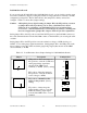
SW1
INTEXT
EXT position—Use this setting to
draw +5 V power from an external
supply connected to connector J8.
SW1
INTEXT