
Barcode Reader User Manual


Installation and Configuration Chapter 2
SC-2043-SG User Manual 2-8 © National Instruments Corporation
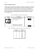
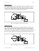
Additionally, there are sockets for eight quarter-bridge completion resistors. When inserted, the
quarter-bridge completion resistors connect to the positive inputs of the instrumentation
amplifiers and the -EXn terminals. To configure a channel for quarter-bridge completion, set the
corresponding bridge completion jumper to the HB position and insert your quarter-bridge
completion resistor into the appropriate sockets. The parts locator diagram, Figure 2-1, shows
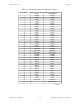
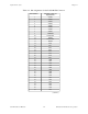
where these quarter-bridge completion resistor sockets are located. Table 2-8 lists the quarter-
bridge completion resistors and corresponding channels.
Table 2-8. Quarter-Bridge Completion Resistors and Corresponding Channels
Channel Resistor
0
1
2
3
4
5
6
7
R52
R36
R20
R6
R54
R37
R23
R9