
Barcode Reader User Manual


© National Instruments Corporation 3-1 SC-2043-SG User Manual
Chapter 3
Signal Connections
This chapter describes the signal connections to the SC-2043-SG board.
I/O Connector Pin Description
Warning: Connections, including any power signals connected to ground and vice versa, that
exceed any of the maximum input or output signal ratings on the SC-2043-SG and
the DAQ board can damage the SC-2043-SG, the DAQ board, and the computer.
National Instruments is
NOT liable for any damages resulting from any such
signal connections.
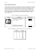
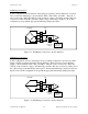
The SC-2043-SG has two male 50-pin I/O connectors to connect it to a DAQ board. These
connectors, J9 and J10, are labeled Lab/1200 and MIO, respectively. The Lab/1200 connector
(J9) carries the signals between the SC-2043-SG and a Lab/1200 board. The MIO connector
(J10) carries the signals between the SC-2043-SG and an MIO or MIO E Series board. You can
use only one of these connectors to interface to a DAQ board at any time. Figure 2-1 shows the
position of these connectors on the SC-2043-SG board.
Notes: If you are connecting to an MIO or MIO E Series board, you must use the MIO
connector. If you are connecting to a Lab/1200 board, you must use the Lab/1200
connector. These connectors are
NOT pin-for-pin compatible and, therefore, you
must be careful
NOT to use the wrong connector.
Connector W9 is reserved for National Instruments internal use only.
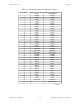
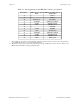
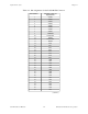
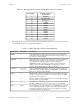
Tables 3-1 and 3-2 show the pin assignments for the SC-2043-SG I/O connectors. These tables
list the pin numbers of the I/O connector and the corresponding signal names for the MIO
connector if you are using an MIO or MIO E Series DAQ board, and for the Lab/1200 connector
if you are using a Lab/1200 Series DAQ board. Tables 3-3 and 3-4 list the MIO and Lab/1200
I/O connector signal summaries, respectively.