
Barcode Reader User Manual


Chapter 3 Signal Connections
© National Instruments Corporation 3-5 SC-2043-SG User Manual
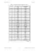
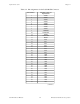
Table 3-2. Pin Assignments for the Lab/1200 I/O Connector (Continued)
Pin Numbers Lab/1200 Connector
Signal Names
38 EXTTRIG
39 EXTUPDATE*
40 EXTCONV*
41 OUTB0
42 GATB0
43 OUTB1
44 GATB1
45 CLKB1
46 OUTB2
47 GATB2
48 CLKB2
49 +5 V†
50 DGND†
† These signals are not routed to screw terminals. All other signals on the I/O connectors are routed directly to
screw terminals (J1–J6) for convenient signal termination.
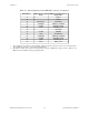
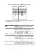
Table 3-3. MIO (J10) I/O Connectors Signal Summary
Signal Name Pin Number Description
AIGND 2 Analog Input Ground—This pin provides the AC noise current return
point for the analog circuitry and for the onboard excitation supply. It is
also routed to a screw terminal.
AISENSE 19 Analog Input Sense—This pin is the reference node for the conditioned
strain gauge bridge signals. It is also routed to a screw terminal to
provide a reference for analog inputs on channels ACH<8..15>.
AISENSE is directly connected to the excitation supply return and is
earth-grounded. This makes AISENSE a low impedance reference;
therefore, all signals referenced to it MUST be floating.
ACH<0..7> 3, 5, 7, 9, 11,
13, 15, 17
Analog Input Channels 0 through 7—These pins carry the conditioned
strain gauge bridge signals (referenced to AISENSE) to the DAQ board.
They are not routed to screw terminals.
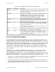
DGND 24
33
Digital Ground—This pin is the reference for the +5 VDC power supply.
It is also routed to a screw terminal to provide a reference for the digital
signals at the screw terminals.
This pin establishes the DC return path for the onboard excitation supply.
It is not routed to a screw terminal.
+5 V 34 +5 VDC Source—This pin provides DC power for the SC-2043-SG from
the MIO or MIO E Series board. It is not routed to a screw terminal.
Others Others The remaining pins are routed directly to screw terminals to provide easy
access to the additional analog, digital, and counter/timer I/O signals of
the DAQ board. Refer to the Signal Connections chapter in your DAQ
board user manual for pin descriptions.