
Barcode Reader User Manual


Chapter 3 Signal Connections
© National Instruments Corporation 3-9 SC-2043-SG User Manual
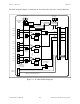
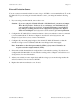
Quarter-Bridge Connection
In this configuration only one strain gauge is used. Bridge completion is provided by the internal
half-bridge completion reference as well as a quarter-bridge completion resistor. This quarter-
bridge completion resistor is equal in value to the external strain gauge element. Insert your
completion resistor in the appropriate sockets. Two lead wires connect the quarter-bridge strain
gauge to screw terminals +EXn and CHn+. If your strain gauge has three lead wires—two wires
at one end and one at the other end—connect the two wires sharing the same end of the strain
gauge at the CHn+ screw terminal, and connect the single wire end to the +EXn screw terminal.
Figure 3-3 shows this configuration, along with the appropriate quarter-bridge completion
resistor and half-bridge jumper placement.
Half-Bridge
Completion
Jumper
Half-Bridge
Completion
Reference
x10
+EX
n
+EX
FB
HB
CH
n
+
CH
n
-
-EX
n
Quarter Bridge
Quarter Bridge
Completion Resistor
(User Installed)
Figure 3-3. Quarter-Bridge Connection to the SC-2043-SG
Offset Nulling
Offset Nulling Adjustment
The SC-2043-SG has circuitry for offset nulling adjustment of Wheatstone bridges. The nulling
circuitry uses the excitation voltage as a reference and operates with full-bridge, half-bridge and
quarter-bridge strain gauge configurations. Each channel has its own nulling circuit, with a
trimming potentiometer to adjust the nulling voltage level, listed in Table 3-6.
Table 3-6. Offset Nulling Adjust Potentiometer and Corresponding Channel
Channel Trimming Potentiometer
0 R62
1 R50
2 R30
3 R14
4 R65
5 R51
6 R33
7 R17