
Barcode Reader User Manual


Signal Connections Chapter 3
SC-2043-SG User Manual 3-10 © National Instruments Corporation
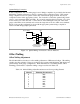
To null the static voltage offset of the system, including the bridge, use the following procedure:
1. Configure and connect your bridge to the selected channel.
2. Read the channel output.
3. While monitoring the output, rotate the trimming potentiometer wiper with a flathead
screwdriver until you reach 0 V.
You have nulled your system offset and are ready for a measurement.
Nulling Range Adjustment
The nulling range of the offset nulling circuitry is approximately ±5 mV referred to input (RTI),
assuming an excitation voltage of 2.5 V. The nulling circuit of each channel has a resistor which
sets this nulling range. You can change the nulling range of the offset nulling circuitry for each
channel by replacing its nulling resistor with a resistor of another value. Therefore, you can mix
your ranges to accommodate each channel requirement. Table 3-7 lists the nulling resistors and
their corresponding channels.
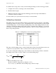
Table 3-7. Nulling Resistor and Corresponding Channel
Channel Nulling Resistor
0 R68
1 R53
2 R34
3 R18
4 R69
5 R55
6 R35
7 R19
The value of all the nulling resistors on the SC-2043-SG is 47 kΩ. Notice that these resistors are
socketed for easy replacement. These sockets best fit a 1/4 W resistor lead size.
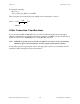
If you want to change the nulling range of any channel, use the following formula to determine
the nulling resistor value you need to achieve your desired nulling range:
REX
100
V RTI
null
desired nulling range
≈
Ω
where:
R
null
is the nulling resistor value,
EX is the excitation voltage (factory-adjusted to 2.5 V),
V
desired nulling range
RTI is the desired nulling range, referred to input.