USER GUIDE AND SPECIFICATIONS USB-6008/6009 This guide describes how to use the National Instruments USB-6008/6009 data acquisition (DAQ) devices and lists specifications. Introduction The NI USB-6008/6009 provides connection to eight analog input (AI) channels, two analog output (AO) channels, 12 digital input/output (DIO) channels, and a 32-bit counter with a full-speed USB interface. Note This manual revision updates naming conventions to reflect the conventions used in NI-DAQmx.
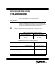
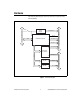
1 17 1 Digital Analog NI USB-6009 16 1 32 8 Inputs, 14-bit, Multifunction I/O USB Cable Strain Relief Figure 1. USB-6008/6009 Figure 2. USB-6008/6009 Back View Safety Guidelines Caution Operate the hardware only as described in these operating instructions. The following section contains important safety information that you must follow when installing and using the USB-6008/6009. Do not operate the USB-6008/6009 in a manner not specified in this document.
Do not operate the device in an explosive atmosphere or where there may be flammable gases or fumes. If you must operate the device in such an environment, it must be in a suitably rated enclosure. If you need to clean the device, use a dry cloth. Make sure that the device is completely dry and free from contaminants before returning it to service. Operate the device only at or below Pollution Degree 2.
• Measurement Category II is for measurements performed on circuits directly connected to the electrical distribution system. This category refers to local-level electrical distribution, such as that provided by a standard wall outlet (for example, 115 V for U.S. or 230 V for Europe). Examples of Measurement Category II are measurements performed on household appliances, portable tools, and similar E Series devices.
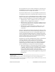
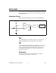
Hardware External Power Supply Vbus +5 V/200 mA PFI 0 USB USB Microcontroller P1.<0..3> P0.<0..7> Digital I/O Terminal Block Full-Speed USB Interface The following block diagram shows key functional components of the USB-6008/6009. +2.5 V/CAL SPI AI <0..7> 12b DAC AO 0 12b DAC AO 1 Analog I/O Terminal Block 8 Channel 12/14b ADC Figure 3.
Setting Up Hardware Complete the following steps to set up the hardware: 1. Install combicon screw terminal blocks by inserting them into the combicon jacks. Note The USB-6008/6009 kit ships with signal labels. You can apply the signal labels to the screw terminal blocks for easy signal identification. 2. Refer to Table 3 and Figure 4 for label orientation and affix the provided signal labels to the screw terminal blocks.
I/O Connector The USB-6008/6009 ships with one detachable screw terminal block for analog signals and one detachable screw terminal block for digital signals. These terminal blocks provide 16 connections that use 16 AWG to 28 AWG wire. Table 3 lists the analog terminal assignments, and Table 4 lists the digital terminal assignments. Table 3.
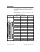
Table 4. Digital Terminal Assignments 32 31 30 29 28 27 26 25 24 23 22 21 20 19 18 17 Module USB-6008/6009 User Guide and Specifications 8 Terminal Signal 17 P0.0 18 P0.1 19 P0.2 20 P0.3 21 P0.4 22 P0.5 23 P0 6 24 P0.7 25 P1.0 26 P1.1 27 P1.2 28 P1.3 29 PFI 0 30 +2.5 V 31 +5 V 32 GND ni.
Signal Descriptions Table 5 describes the signals available on the I/O connectors. Table 5. Signal Descriptions Signal Name Reference Direction Description — — Ground—The reference point for the single-ended AI measurements, bias current return point for differential mode measurements, AO voltages, digital signals at the I/O connector, +5 VDC supply, and the +2.5 VDC reference. GND AI <0..
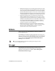
Analog Input You can connect analog input signals to the USB-6008/6009 through the I/O connector. Refer to Table 5 for more information about connecting analog input signals. Analog Input Circuitry Figure 5 illustrates the analog input circuitry of the USB-6008/6009. +2.5 VREF 30.9 kΩ MUX PGA ADC AI FIFO 127 kΩ AI 39.2 kΩ Input Range Selection Figure 5. Analog Input Circuitry MUX The USB 6008/6009 has one analog-to-digital converter (ADC).
AI FIFO The USB-6008/6009 can perform both single and multiple A/D conversions of a fixed or infinite number of samples. A first-in-first-out (FIFO) buffer holds data during AI acquisitions to ensure that no data is lost. Analog Input Modes You can configure the AI channels on the USB-6008/6009 to take single-ended or differential measurements. Refer to Table 5 for more information about I/O connections for single-ended or differential measurements.
20 15 Amplitude (V) 10 5 AI 1 0 AI 5 Result –5 –10 –15 –20 Figure 7. Example of a Differential 20 V Measurement Connecting a signal greater than ±10 V on either pin results in a clipped output. 20 15 Amplitude (V) 10 5 AI 1 0 AI 5 Result –5 –10 –15 –20 Figure 8.
AI Voltage Source USB-6008/6009 GND Figure 9. Connecting a Reference Single-Ended Voltage Signal Digital Trigger When an AI task is defined, you can configure PFI 0 as a digital trigger input. When the digital trigger is enabled, the AI task waits for a rising edge on PFI 0 before starting the acquisition. To use ai/Start Trigger with a digital source, specify PFI 0 as the source and select rising edge.
Connecting Analog Output Loads To connect loads to the USB-6008/6009, connect the positive lead of the load to the AO terminal, and connect the ground of the load to a GND terminal. AO Load USB-6008/6009 GND Figure 11. Connecting a Load Minimizing Glitches on the Output Signal When you use a DAC to generate a waveform, you may observe glitches in the output signal. These glitches are normal; when a DAQ switches from one voltage to another, it produces glitches due to released charges.
+5 V 1 LED P0.0 P0.1 P0.2 P0.3 P0.4 P0.5 P0.6 P0.7 LED 2 3 +5 V TTL Signal 4 Switch GND I/O Connector 1 2 3 4 P0.0 configured as an open collector digital output driving a LED P0.2 configured as a active drive digital output driving a LED P0.4 configured as a digital input receiving a TTL signal from a gated invertor P0.7 configured as a digital input receiving a 0 V or 5 V signal from a switch Figure 12.
USB-6008/6009 +5 V +5 V Re Rp 4.7 KΩ Onboard Resistor External Pull-up Resistor Port Pad P0.0 Rl Load GND A Figure 13. Example of Connecting External User-Provided Resistor Complete the following steps to determine the value of the user-provided pull-up resistor: 1. Place an ammeter in series with the load. 2. Place a variable resistor between the digital output line and the +5 V. 3. Adjust the variable resistor until the ammeter current reads as the intended current.
National Instruments has several signal conditioning solutions for digital applications requiring high current drive. • If you configure a DIO line as an input, do not drive the line with voltages outside of its normal operating range. The DIO lines have a smaller operating range than the AI signals. • Treat the DAQ device as you would treat any static sensitive device. Always properly ground yourself and the equipment when handling the DAQ device or connecting to it.
Specifications The following specifications are typical at 25 °C, unless otherwise noted. Analog Input Converter type ........................................Successive approximation Analog inputs..........................................8 single-ended, 4 differential, software selectable Input resolution USB-6008 ........................................12 bits differential, 11 bits single-ended USB-6009 ........................................
Trigger source ........................................ Software or external digital trigger System noise USB-6008, differential.................... 1.47 mVrms USB-6009, single-ended ................. 2.93 mVrms USB-6009, differential.................... 0.37 mVrms USB-6009, single-ended ................. 0.73 mVrms Absolute accuracy at full scale, single ended Range Typical at 25 °C (mV) Maximum over Temperature (mV) +10 14.
Output current drive................................5 mA Power-on state ........................................0 V Slew rate .................................................1 V/µs Short circuit current ................................50 mA Absolute accuracy (no load) ...................7 mV typical, 36.4 mV maximum at full scale Digital I/O Digital I/O P0.<0..7> .........................................8 lines PI.<0..3> ..........................................4 lines Direction control..................
Digital logic levels Level Input low voltage Input high voltage Input leakage current Output low voltage (I = 8.5 mA) Output high voltage Active drive (push-pull), I = –8.5mA Open collector (open-drain), I = –0.6mA, nominal Open collector (open-drain), I = –8.5mA, with external pull-up resistor Min Max Units –0.3 2.0 — 0.8 5.8 50 V V µA — 0.8 V 2.0 2.0 2.0 3.5 5.0 — V V V External Voltage +5 V output (200 mA maximum) .......... +5 V typical, +4.85 V minimum +2.5 V output (1 mA maximum) ........
Power Requirements USB 4.10 to 5.25 VDC.............................80 mA typical, 500 mA max USB suspend ...................................300 µA typical, 500 µA max Physical Characteristics If you need to clean the module, wipe it with a dry towel. Dimensions Without connectors..........................6.35 cm × 8.51 cm × 2.31 cm (2.50 in. × 3.35 in. × 0.91 in.) With connectors...............................8.18 cm × 8.51 cm × 2.31 cm (3.22 in. × 3.35 in. × 0.91 in.) I/O connectors......................
Voltages Connect only voltages that are within these limits. Channel-to-GND.................................... ±30 V max, Measurement Category I Measurement Category I is for measurements performed on circuits not directly connected to the electrical distribution system referred to as MAINS voltage. MAINS is a hazardous live electrical supply system that powers equipment. This category is for measurements of voltages from specially protected secondary circuits.
Electromagnetic Compatibility Emissions................................................EN 55011 Class A at 10 m FCC Part 15A above 1 GHz Immunity ................................................Industrial levels per EN 61326:1997 + A2:2001, Table 1 EMC/EMI ...............................................CE, C-Tick, and FCC Part 15 (Class A) Compliant Note The USB-6008/6009 may experience temporary variations in analog input readings when exposed to radiated and conducted RF noise.
National Instruments corporate headquarters is located at 11500 North Mopac Expressway, Austin, Texas, 78759-3504. National Instruments also has offices located around the world to help address your support needs. For telephone support in the United States, create your service request at ni.com/support and follow the calling instructions or dial 512 795 8248.