DAQ M Series NI USB-621x User Manual Bus-Powered M Series USB Devices NI USB-621x User Manual August 2006 371931A-01
Support Worldwide Technical Support and Product Information ni.
Important Information Warranty The USB-6210, USB-6211, USB-6215, and USB-6218 devices are warranted against defects in materials and workmanship for a period of three years from the date of shipment, as evidenced by receipts or other documentation. National Instruments will, at its option, repair or replace equipment that proves to be defective during the warranty period. This warranty includes parts and labor.
NATIONAL INSTRUMENTS PRODUCTS ARE INCORPORATED IN A SYSTEM OR APPLICATION, INCLUDING, WITHOUT LIMITATION, THE APPROPRIATE DESIGN, PROCESS AND SAFETY LEVEL OF SUCH SYSTEM OR APPLICATION.
Contents About This Manual Conventions ...................................................................................................................xiii Related Documentation..................................................................................................xiv NI-DAQmx for Windows................................................................................xiv LabVIEW ........................................................................................................
Contents Chapter 4 Analog Input Analog Input Circuitry .................................................................................................. 4-1 Analog Input Range....................................................................................................... 4-2 Analog Input Ground-Reference Settings ..................................................................... 4-3 Configuring AI Ground-Reference Settings in Software................................
Contents AI Pause Trigger Signal ..................................................................................4-23 Using a Digital Source ......................................................................4-23 Getting Started with AI Applications in Software.........................................................4-24 Chapter 5 Connecting AI Signals on the USB-6210/6211 Devices Connecting Floating Signal Sources..............................................................................
Contents Chapter 7 Analog Output Analog Output Circuitry................................................................................................ 7-1 AO Range ...................................................................................................................... 7-2 Minimizing Glitches on the Output Signal.................................................................... 7-2 Analog Output Data Generation Methods.....................................................................
Contents Pulse-Width Measurement ..............................................................................9-5 Single Pulse-Width Measurement.....................................................9-5 Buffered Pulse-Width Measurement.................................................9-5 Period Measurement........................................................................................9-6 Single Period Measurement ..............................................................
Contents Counter n A, Counter n B, and Counter n Z Signals ...................................... 9-28 Routing Signals to A, B, and Z Counter Inputs................................ 9-28 Counter n Up_Down Signal............................................................................ 9-28 Counter n HW Arm Signal.............................................................................. 9-28 Routing Signals to Counter n HW Arm Input ..................................
Contents Chapter 11 Isolation and Digital Isolators Digital Isolation .............................................................................................................11-2 Benefits of an Isolated DAQ Device .............................................................................11-2 Reducing Common-Mode Noise ...................................................................................11-2 Creating an AC Return Path ....................................................................
Contents Appendix B Troubleshooting Appendix C Technical Support and Professional Services Glossary Index Device Pinouts Figure A-1. Figure A-2. Figure A-3. NI USB-621x User Manual USB-6210 Pinout .................................................................................. A-2 USB-6211/6215 Pinout ......................................................................... A-5 USB 6218 Pinout .................................................................................. A-8 xii ni.
About This Manual The NI 621x User Manual contains information about using the National Instruments USB-621x data acquisition (DAQ) devices with NI-DAQmx 8.3 and later. NI 621x devices feature up to 32 analog input (AI) channels, up to two analog output (AO) channels, up to eight lines of digital input (DI), up to eight lines of digital output (DO), and two counters.
About This Manual Related Documentation Each application software package and driver includes information about writing applications for taking measurements and controlling measurement devices. The following references to documents assume you have NI-DAQ 8.3 or later, and where applicable, version 7.0 or later of the NI application software.
About This Manual tools. Refer to the following locations on the Contents tab of the LabVIEW Help for information about NI-DAQmx: • Getting Started»Getting Started with DAQ—Includes overview information and a tutorial to learn how to take an NI-DAQmx measurement in LabVIEW using the DAQ Assistant. • VI and Function Reference»Measurement I/O VIs and Functions—Describes the LabVIEW NI-DAQmx VIs and properties.
About This Manual .NET Languages without NI Application Software The NI Measurement Studio Help contains function reference and measurement concepts for using the Measurement Studio NI-DAQmx .NET and Visual C++ class libraries. This help collection is integrated into the Visual Studio .NET documentation. In Visual Studio .NET, select Help»Contents. Note You must have Visual Studio .NET installed to view the NI Measurement Studio Help.
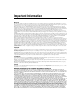
1 Getting Started Figure 1-1.
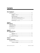
Chapter 1 Getting Started Figure 1-2. USB-6215/6218 NI 621x devices feature up to 32 analog input (AI) channels, up to two analog output (AO) channels, 8 lines of digital input (DI), 8 lines of digital output (DO), and two counters. If you have not already installed your device, refer to the NI-DAQmx for USB Devices Getting Started Guide. For specifications, refer to the NI 621x Specifications document on ni.com/manuals.
Chapter 1 Getting Started Installing the Hardware The NI-DAQmx for USB Devices Getting Started Guide contains non-software-specific information about how to install USB devices. Device Pinouts Refer to Appendix A, Device-Specific Information, for NI 621x device pinouts. Device Specifications Refer to the NI 621x Specifications, available on the NI-DAQ Device Document Browser or ni.com/manuals, for more detailed information about NI 621x devices.
2 DAQ System Overview Figure 2-1 shows a typical DAQ system, which includes sensors, transducers, signal conditioning devices, cables that connect the various devices to the accessories, the M Series device, programming software, and PC. The following sections cover the components of a typical DAQ system. DAQ Hardware DAQ Software Personal Computer or Laptop Figure 2-1.
Chapter 2 DAQ System Overview Isolation Barrier (USB-6215 and USB-6218 devices only) Analog Input I/O Connector Analog Output Digital Routing and Clock Generation Digital I/O Digital Isolators Bus Interface Bus Counters PFI Figure 2-2. USB-621x Block Diagram DAQ-STC2 The DAQ-STC2 implements a high-performance digital engine for M Series data acquisition hardware.
Chapter 2 DAQ System Overview Factory-calibration constants are permanently stored in an onboard EEPROM and cannot be modified. When you self-calibrate the device, software stores new constants in a user-modifiable section of the EEPROM. To return a device to its initial factory calibration settings, software can copy the factory-calibration constants to the user-modifiable section of the EEPROM. Refer to the NI-DAQmx Help or the LabVIEW 8.x Help for more information about using calibration constants.
Chapter 2 DAQ System Overview Programming Devices in Software National Instruments measurement devices are packaged with NI-DAQ driver software, an extensive library of functions and VIs you can call from your application software, such as LabVIEW or LabWindows/CVI, to program all the features of your NI measurement devices. Driver software has an application programming interface (API), which is a library of VIs, functions, classes, attributes, and properties for creating applications for your device.
3 Connector Information The I/O Connector Signal Descriptions and +5 V Power sections contain information about NI 621x connectors. Refer to Appendix A, Device-Specific Information, for device I/O connector pinouts. I/O Connector Signal Descriptions Table 3-1 describes the signals found on the I/O connectors. Not all signals are available on all devices. Table 3-1.
Chapter 3 Connector Information Table 3-1. I/O Connector Signals (Continued) Signal Name Reference Direction Description AO GND — — Analog Output Ground—AO GND is the reference for AO <0..1>. All three ground references—AI GND, AO GND, and D GND—are connected on the device. D GND — — Digital Ground—D GND supplies the reference for PFI <0..15>/P0/P1 and +5 V. All three ground references—AI GND, AO GND, and D GND—are connected on the device.
Chapter 3 Connector Information +5 V Power as an Input If you have high current loads for the digital outputs to drive, you can exceed the 50 mA internal limit by connecting an external +5 V power source to the +5 V terminals. These terminals are protected against undervoltage and overvoltage, and they have a 350 mA self-resetting fuse to protect them from short circuit conditions.
4 Analog Input Figure 4-1 shows the analog input circuitry of NI 621x devices. I/O Connector Isolation Barrier (USB-6215 and USB-6218 devices only) AI <0..n> MUX DIFF, RSE, or NRSE NI-PGIA ADC AI FIFO Digital Isolators AI Data AI SENSE Input Range Selection AI GND AI Terminal Configuration Selection Figure 4-1. M Series Analog Input Circuitry Analog Input Circuitry I/O Connector You can connect analog input signals to the M Series device through the I/O connector.
Chapter 4 Analog Input Ground-Reference Settings The analog input ground-reference settings circuitry selects between differential, referenced single-ended, and non-referenced single-ended input modes. Each AI channel can use a different mode. Instrumentation Amplifier (NI-PGIA) The NI programmable gain instrumentation amplifier (NI-PGIA) is a measurement and instrument class amplifier that minimizes settling times for all input ranges.
Chapter 4 Analog Input calibration method improves absolute accuracy, but it increases the nominal resolution of input ranges by about 5% over what the formula shown above would indicate. Choose an input range that matches the expected input range of your signal. A large input range can accommodate a large signal variation, but reduces the voltage resolution. Choosing a smaller input range improves the voltage resolution, but may result in the input signal going out of range.
Chapter 4 Analog Input The AI ground-reference setting determines how you should connect your AI signals to the NI 621x device. Refer to Chapter 5, Connecting AI Signals on the USB-6210/6211 Devices, section for more information. Ground-reference settings are programmed on a per-channel basis. For example, you might configure the device to scan 12 channels—four differentially-configured channels and eight single-ended channels.
Chapter 4 Analog Input pairs that form differential input channels, refer to the I/O Connector Signal Descriptions section of Chapter 3, Connector Information. Caution The maximum input voltages rating of AI signals with respect to AI GND (and for differential signals with respect to each other) are listed in the specifications document for your device. Exceeding the maximum input voltage of AI signals distorts the measurement results.
Chapter 4 Analog Input Multichannel Scanning Considerations M Series devices can scan multiple channels at high rates and digitize the signals accurately. However, you should consider several issues when designing your measurement system to ensure the high accuracy of your measurements. In multichannel scanning applications, accuracy is affected by settling time.
Chapter 4 Analog Input If your source impedance is high, you can decrease the scan rate to allow the NI-PGIA more time to settle. Another option is to use a voltage follower circuit external to your DAQ device to decrease the impedance seen by the DAQ device. Refer to the KnowledgeBase document, How Do I Create a Buffer to Decrease the Source Impedance of My Analog Input Signal?, by going to ni.com/info and entering the info code rdbbis.
Chapter 4 Analog Input You can connect channel 2 to AI GND (or you can use the internal ground signal; refer to Internal Channels in the NI-DAQmx Help). Set the input range of channel 2 to –200 mV to 200 mV to match channel 1. Then scan channels in the order: 0, 2, 1. Inserting a grounded channel between signal channels improves settling time because the NI-PGIA adjusts to the new input range setting faster when the input is grounded.
Chapter 4 Analog Input Example 2 If the time relationship between channels is not critical, you can sample from the same channel multiple times and scan less frequently. For example, suppose an application requires averaging 100 points from channel 0 and averaging 100 points from channel 1. You could alternate reading between channels—that is, read one point from channel 0, then one point from channel 1, and so on. You also could read all 100 points from channel 0 then read 100 points from channel 1.
Chapter 4 Analog Input Buffered In a buffered acquisition, data is moved from the DAQ device’s onboard FIFO memory to a PC buffer using USB signal streams or programmed I/O before it is transferred to application memory. Buffered acquisitions typically allow for much faster transfer rates than non-buffered acquisitions because data is moved in large blocks, rather than one point at a time. One property of buffered I/O operations is the sample mode. The sample mode can be either finite or continuous.
Chapter 4 Analog Input A digital trigger can initiate these actions. All NI 621x devices support digital triggering. NI 621x devices do not support analog triggering. Field Wiring Considerations Environmental noise can seriously affect the measurement accuracy of the device if you do not take proper care when running signal wires between signal sources and the device. The following recommendations apply mainly to AI signal routing to the device, although they also apply to signal routing in general.
Chapter 4 Analog Input Analog Comparison Event Ctr n Internal Output 20 MHz Timebase ai/SampleClock SW Pulse ai/SampleClock Timebase Programmable Clock Divider 100 kHz Timebase ai/ConvertClock Ctr n Internal Output ai/ConvertClock Timebase Programmable Clock Divider Figure 4-4. Analog Input Timing Options M Series devices use ai/SampleClock and ai/ConvertClock to perform interval sampling.
Chapter 4 Analog Input NI-DAQmx chooses the default convert rate to allow for the maximum settling time between conversions. Typically, this rate is the sampling rate for the task multiplied by the number of channels in the task. Note The sampling rate is the fastest you can acquire data on the device and still achieve accurate results.
Chapter 4 Analog Input ai/StartTrigger ai/ReferenceTrigger n/a ai/SampleClock ai/ConvertClock Scan Counter 3 2 1 0 2 2 2 1 0 Figure 4-7. Pretriggered Data Acquisition Example If an ai/ReferenceTrigger pulse occurs before the specified number of pretrigger samples are acquired, the trigger pulse is ignored. Otherwise, when the ai/ReferenceTrigger pulse occurs, the sample counter value decrements until the specified number of posttrigger samples have been acquired.
Chapter 4 Analog Input Using an Internal Source One of the following internal signals can drive ai/SampleClock. • Counter n Internal Output • AI Sample Clock Timebase (divided down) • A software pulse A programmable internal counter divides down the sample clock timebase. Using an External Source Use the external signals PFI <0..3> or PFI <8..11> as the source of ai/SampleClock. Routing AI Sample Clock Signal to an Output Terminal You can route ai/SampleClock out to any PFI <4..7> or PFI <12..
Chapter 4 Analog Input to AI Convert Clock Signal for more information about the timing requirements between ai/ConvertClock and ai/SampleClock. Figure 4-8 shows the relationship of ai/SampleClock to ai/StartTrigger. ai/SampleClockTimebase ai/StartTrigger ai/SampleClock Delay From Start Trigger Figure 4-8.
Chapter 4 Analog Input channel to allow for adequate settling time. This scheme enables the channels to approximate simultaneous sampling and still allow for adequate settling time. If the AI Sample Clock rate is too fast to allow for this 10 µs of padding, NI-DAQmx chooses the conversion rate so that the AI Convert Clock pulses are evenly spaced throughout the sample. To explicitly specify the conversion rate, use AI Convert Clock Rate DAQmx Timing property node or function.
Chapter 4 Analog Input Figure 4-9 shows the relationship of ai/SampleClock to ai/ConvertClock. ai/ConvertClockTimebase ai/SampleClock ai/ConvertClock Delay From Sample Clock Convert Period Figure 4-9. ai/SampleClock and ai/ConvertClock Other Timing Requirements The sample and conversion level timing of M Series devices work such that clock signals are gated off unless the proper timing requirements are met.
Chapter 4 Analog Input ai/SampleClock ai/ConvertClock Channel Measured 0 1 2 3 0 1 2 3 0 1 2 3 Sample #1 Sample #2 Sample #3 • Sample Clock Too Fast for Convert Clock • Sample Clock Pulses are Gated Off Figure 4-10. ai/SampleClock Too Fast ai/SampleClock ai/ConvertClock Channel Measured 0 1 2 3 0 1 2 3 0 1 2 3 Sample #1 Sample #2 Sample #3 • Convert Clock Too Fast for Sample Clock • Convert Clock Pulses are Gated Off Figure 4-11.
Chapter 4 Analog Input ai/SampleClock ai/ConvertClock Channel Measured 0 1 2 3 0 1 2 3 0 1 2 3 Sample #1 Sample #2 Sample #3 • Properly Matched Sample Clock and Convert Clock Figure 4-13. ai/SampleClock and ai/ConvertClock Properly Matched It is also possible to use a single external signal to drive both ai/SampleClock and ai/ConvertClock at the same time. In this mode, each tick of the external clock will cause a conversion on the ADC. Figure 4-14 shows this timing relationship.
Chapter 4 Analog Input AI Hold Complete Event Signal The AI Hold Complete Event (ai/HoldCompleteEvent) signal generates a pulse after each A/D conversion begins. You can route ai/HoldCompleteEvent out to any PFI <4..8> or PFI <12..15> terminal. The polarity of ai/HoldCompleteEvent is software-selectable, but is typically configured so that a low-to-high leading edge can clock external AI multiplexers indicating when the input signal has been sampled and can be removed.
Chapter 4 Analog Input The device also uses ai/StartTrigger to initiate pretriggered DAQ operations. In most pretriggered applications, a software trigger generates ai/StartTrigger. Refer to the AI Reference Trigger Signal section for a complete description of the use of ai/StartTrigger and ai/ReferenceTrigger in a pretriggered DAQ operation. AI Reference Trigger Signal Use a reference trigger (ai/ReferenceTrigger) signal to stop a measurement acquisition.
Chapter 4 Analog Input Using a Digital Source To use ai/ReferenceTrigger with a digital source, specify a source and an edge. The source can be the PFI <0..3> or PFI <8..11> signals. The source also can be one of several internal signals on your DAQ device. Refer to Device Routing in MAX in the NI-DAQmx Help or the LabVIEW 8.x Help for more information. You also can specify whether the measurement acquisition stops on the rising edge or falling edge of ai/ReferenceTrigger.
Chapter 4 Analog Input Getting Started with AI Applications in Software You can use the M Series device in the following analog input applications. • Single-point analog input • Finite analog input • Continuous analog input You can perform these applications through DMA, interrupt, or programmed I/O data transfer mechanisms. Some of the applications also use start, reference, and pause triggers.
Connecting AI Signals on the USB-6210/6211 Devices 5 Table 5-1 summarizes the recommended input configuration for both types of signal sources on NI 6210/6211 devices.
Chapter 5 Connecting AI Signals on the USB-6210/6211 Devices Table 5-1.
Chapter 5 Connecting AI Signals on the USB-6210/6211 Devices Connecting Floating Signal Sources What Are Floating Signal Sources? A floating signal source is not connected to the building ground system, but has an isolated ground-reference point. Some examples of floating signal sources are outputs of transformers, thermocouples, battery-powered devices, optical isolators, and isolation amplifiers. An instrument or device that has an isolated output is a floating signal source.
Chapter 5 Connecting AI Signals on the USB-6210/6211 Devices In the single-ended modes, more electrostatic and magnetic noise couples into the signal connections than in DIFF configurations. The coupling is the result of differences in the signal path. Magnetic coupling is proportional to the area between the two signal conductors. Electrical coupling is a function of how much the electric field differs between the two conductors.
Chapter 5 Connecting AI Signals on the USB-6210/6211 Devices Using Differential Connections for Floating Signal Sources It is important to connect the negative lead of a floating source to AI GND (either directly or through a bias resistor). Otherwise, the source may float out of the maximum working voltage range of the NI-PGIA and the DAQ device returns erroneous data.
Chapter 5 Connecting AI Signals on the USB-6210/6211 Devices AI+ Floating Signal Source + Vs – AI– R is about 100 times source impedance of sensor R AI SENSE AI GND Figure 5-2. Differential Connections for Floating Signal Sources with Single Bias Resistor You can fully balance the signal path by connecting another resistor of the same value between the positive input and AI GND on the USB-621x device, as shown in Figure 5-3.
Chapter 5 Connecting AI Signals on the USB-6210/6211 Devices AI+ Floating Signal Source + Bias Resistors (see text) Vs + Instrumentation Amplifier – PGIA + AI– – Measured Voltage Vm – Bias Current Return Paths Input Multiplexers AI SENSE AI GND I/O Connector M Series Device Configured in DIFF Mode Figure 5-3. Differential Connections for Floating Signal Sources with Balanced Bias Resistors Both inputs of the NI-PGIA require a DC path to ground in order for the NI-PGIA to work.
Chapter 5 Connecting AI Signals on the USB-6210/6211 Devices inputs; be aware that there is some gain error from loading down the source, as shown in Figure 5-4. AC Coupling AI+ AC Coupled Floating Signal Source + Vs – AI– AI SENSE AI GND Figure 5-4.
Chapter 5 Connecting AI Signals on the USB-6210/6211 Devices connection is shared with all channels rather than being cabled in a twisted pair with the AI+ signal. Using the DAQ Assistant, you can configure the channels for RSE or NRSE input modes. Refer to the Configuring AI Ground-Reference Settings in Software section of Chapter 4, Analog Input, for more information about the DAQ Assistant.
Chapter 5 Connecting AI Signals on the USB-6210/6211 Devices The difference in ground potential between two instruments connected to the same building power system is typically between 1 and 100 mV, but the difference can be much higher if power distribution circuits are improperly connected. If a grounded signal source is incorrectly measured, this difference can appear as measurement error.
Chapter 5 Connecting AI Signals on the USB-6210/6211 Devices In the single-ended modes, more electrostatic and magnetic noise couples into the signal connections than in DIFF configurations. The coupling is the result of differences in the signal path. Magnetic coupling is proportional to the area between the two signal conductors. Electrical coupling is a function of how much the electric field differs between the two conductors.
Chapter 5 Connecting AI Signals on the USB-6210/6211 Devices Using Differential Connections for Ground-Referenced Signal Sources Figure 5-7 shows how to connect a ground-referenced signal source to the USB-6210/6211 device configured in DIFF mode.
Chapter 5 Connecting AI Signals on the USB-6210/6211 Devices Using Non-Referenced Single-Ended (NRSE) Connections for Ground-Referenced Signal Sources Figure 5-8 shows how to connect ground-reference signal sources to the USB-6210/6211 device in NRSE mode. I/O Connector GroundReferenced Signal Source AI <0..15> or AI <16..
6 Connecting AI Signals on the USB-6215/6218 Devices You can connect the USB-6215/6218 directly to a variety of devices and other signal sources. Make sure the devices you connect to the USB-6215/6218 are compatible with the input specifications of the module. When connecting various sources to the USB-6215/6218, you can use differential, single-ended, or a combination of single-ended and differential connections. Refer to Figures 6-1, 6-2, and 6-3 for diagrams of each connection type.
Chapter 6 Connecting AI Signals on the USB-6215/6218 Devices Table 6-1. I/O Connector Signals (Continued) Channel Signal + Signal – 3 A I3 AI 11 4 A I4 AI 12 5 A I5 AI 13 6 A I6 AI 14 7 A I7 AI 15 16* AI 16 AI 24 17* AI 17 AI 25 18* AI 18 AI 26 19* AI 19 AI 27 20* AI 20 AI 28 21* AI 21 AI 29 22* AI 22 AI 30 23* AI 23 AI 31 * USB-6218 devices only. Refer to Figure 6-1 for an illustration of a differential connection configuration.
Chapter 6 Connecting AI Signals on the USB-6215/6218 Devices The differential connection configuration allows the common-mode noise voltage, Vcm, to be rejected during the measurement of V1. You must connect the negative lead of your sensors and AI GND to a local ground signal on your system. Referenced Single-Ended (RSE) Measurements Using the RSE measurement configuration allows the USB-6215/6218 to take measurements on all AI channels when all channels share a common ground.
Chapter 6 Connecting AI Signals on the USB-6215/6218 Devices Non-Referenced Single-Ended (NRSE) Measurements To reach a compromise between RSE and differential measurements, you can use an NRSE measurement configuration. This configuration allows for a remote sense for the negative (–) input of the programmable gain instrumentation amplifier (PGIA) that is shared among all channels configured for NRSE mode.
7 Analog Output Many M Series devices have analog output functionality. NI 621x devices that support analog output have two AO channels controlled by a single clock and capable of waveform generation. Refer to Appendix A, Device-Specific Information, for information about the capabilities of your device. Figure 7-1 shows the analog output circuitry of M Series devices.
Chapter 7 Analog Output DACs. It allows you to download the points of a waveform to your M Series device without host computer interaction. AO Sample Clock The AO Sample Clock signal reads a sample from the DAC FIFO and generates the AO voltage. AO Range The AO Range is ±10 V for NI 621x devices. Minimizing Glitches on the Output Signal When you use a DAC to generate a waveform, you may observe glitches on the output signal.
Chapter 7 Analog Output Hardware-timed generations have several advantages over software-timed acquisitions: • The time between samples can be much shorter. • The timing between samples can be deterministic. • Hardware-timed acquisitions can use hardware triggering. Hardware-timed operations can be buffered or non-buffered.
Chapter 7 Analog Output the buffer at a fast enough rate to keep up with the generation, the buffer will underflow and cause an error. Analog Output Digital Triggering Analog output supports two different triggering actions: • Start trigger • Pause trigger A digital trigger can initiate these actions on the USB-621x devices. Refer to the AO Start Trigger Signal and AO Pause Trigger Signal sections for more information about these triggering actions. Connecting Analog Output Signals AO <0..
Chapter 7 Analog Output Analog Output Timing Signals Figure 7-3 summarizes all of the timing options provided by the analog output timing engine. PFI PFI ao/SampleClock Ctr n Internal Output ao/SampleClock Timebase 20 MHz Timebase Programmable Clock Divider 100 kHz Timebase SampleClock Timebase Divisor Figure 7-3. Analog Output Timing Options USB M Series devices feature the following AO (waveform generation) timing signals.
Chapter 7 Analog Output The source also can be one of several internal signals on your DAQ device. Refer to Device Routing in MAX in the NI-DAQmx Help or the LabVIEW 8.x Help for more information. You also can specify whether the waveform generation begins on the rising edge or falling edge of ao/StartTrigger. Routing AO Start Trigger Signal to an Output Terminal You can route ao/StartTrigger out to any PFI <4..7> or PFI <12..15> terminal. The output is an active high pulse.
Chapter 7 Analog Output The source also can be one of several other internal signals on your DAQ device. Refer to Device Routing in MAX in the NI-DAQmx Help or the LabVIEW 8.x Help for more information. You also can specify whether the samples are paused when ao/PauseTrigger is at a logic high or low level. AO Sample Clock Signal Use the AO Sample Clock (ao/SampleClock) signal to initiate AO samples. Each sample updates the outputs of all of the DACs.
Chapter 7 Analog Output Figure 7-5 shows the relationship of ao/SampleClock to ao/StartTrigger. ao/SampleClockTimebase ao/StartTrigger ao/SampleClock Delay From Start Trigger Figure 7-5. ao/SampleClock and ao/StartTrigger AO Sample Clock Timebase Signal The AO Sample Clock Timebase (ao/SampleClockTimebase) signal is divided down to provide a source for ao/SampleClock.
Chapter 7 Analog Output Getting Started with AO Applications in Software You can use an NI 621x device in the following analog output applications. • Single-point (on-demand) generation • Finite generation • Continuous generation • Waveform generation You can perform these generations through programmed I/O or USB Signal Stream data transfer mechanisms. Some of the applications also use start triggers and pause triggers.
8 Digital I/O NI 621x devices have eight static digital input lines, P0.<0..7>. These lines also can be used as PFI inputs. NI 621x devices have eight static digital output lines, P1.<0..8>.These lines also can be used as PFI output. By default the digital output lines are disabled (high impedance with a 47 kΩ pull down resistor) on power up. Software can enable or disable the entire port (software cannot enable individual lines).
Chapter 8 Digital I/O The voltage input and output levels and the current drive levels of the DIO lines are listed in the specifications of your device. Static DIO You can use static DI and DO lines to monitor or control digital signals. All samples of static DI lines and updates of DO lines are software-timed. I/O Protection Each DI, DO, and PFI signal is protected against overvoltage, undervoltage, and overcurrent conditions as well as ESD events.
Chapter 8 Digital I/O Connecting Digital I/O Signals The DI and DO signals, P0.<0..7> and P1.<0..7> are referenced to D GND. Digital input applications include receiving TTL signals and sensing external device states, such as the state of the switch shown in the figure. Digital output applications include sending TTL signals and driving external devices, such as the LED shown in Figure 8-2. +5 V Isolation Barrier (USB-6215 and USB-6218 devices only) LED P1.<0..3> TTL Signal Digital Isolators P0.<0..
Chapter 8 Digital I/O Getting Started with DIO Applications in Software You can use the M Series device in the following digital I/O applications: • Static digital input • Static digital output • Digital waveform generation • Digital waveform acquisition • DI change detection Note For more information about programming digital I/O applications and triggers in software, refer to the NI-DAQmx Help or the LabVIEW 8.x Help. NI USB-621x User Manual 8-4 ni.
9 Counters M Series devices have two general-purpose 32-bit counter/timers and one frequency generator, as shown in Figure 9-1. The general-purpose counter/timers can be used for many measurement and pulse generation applications.
Chapter 9 Counters The counters have seven input signals, although in most applications only a few inputs are used. For information about connecting counter signals, refer to the Default Counter/Timer Pinouts section. Counter Input Applications Counting Edges In edge counting applications, the counter counts edges on its Source after the counter is armed. You can configure the counter to count rising or falling edges on its Source input. You also can control the direction of counting (up or down).
Chapter 9 Counters Counter Armed Pause Trigger (Pause When Low) SOURCE Counter Value 0 0 1 2 3 4 5 Figure 9-3. Single Point (On-Demand) Edge Counting with Pause Trigger Buffered (Sample Clock) Edge Counting With buffered edge counting (edge counting using a sample clock), the counter counts the number of edges on the Source input after the counter is armed. The value of the counter is sampled on each active edge of a sample clock. A USB Signal Stream transfers the sampled values to host memory.
Chapter 9 Counters Non-Cumulative Buffered Edge Counting Non-cumulative edge counting is similar to buffered (sample clock) edge counting. However, the counter resets after each active edge of the Sample Clock. You can route the Sample Clock to the Gate input of the counter. Figure 9-5 shows an example of non-cumulative buffered edge counting. Sample Clock (Sample on Rising Edge) Counter Armed SOURCE Counter Value 0 1 2 1 2 Buffer 2 3 1 2 3 2 3 1 2 3 3 Figure 9-5.
Chapter 9 Counters Pulse-Width Measurement In pulse-width measurements, the counter measures the width of a pulse on its Gate input signal. You can configure the counter to measure the width of high pulses or low pulses on the Gate signal. You can route an internal or external periodic clock signal (with a known period) to the Source input of the counter. The counter counts the number of rising (or falling) edges on the Source signal while the pulse on the Gate signal is active.
Chapter 9 Counters The counter counts the number of edges on the Source input while the Gate input remains active. On each trailing edge of the Gate signal, the counter stores the count in a hardware save register. A USB Signal Stream transfers the stored values to host memory. Figure 9-7 shows an example of a buffered pulse-width measurement. GATE SOURCE 0 COUNTER VALUE 1 2 3 1 2 3 BUFFER 3 3 2 2 Figure 9-7.
Chapter 9 Counters Single Period Measurement With single period measurement, the counter counts the number of rising (or falling) edges on the Source input occurring between two active edges of the Gate input. On the second active edge of the Gate input, the counter stores the count in a hardware save register and ignores other edges on the Gate and Source inputs. Software then reads the stored count. Figure 9-8 shows an example of a single period measurement.
Chapter 9 Counters Counter Armed GATE SOURCE 1 Counter Value 2 3 1 2 3 3 3 1 3 3 3 Buffer Time N t0 t1 t2 t3 Figure 9-9. Buffered Period Measurement Table 9-1. Time N Descriptions t0 At t0, the counter is armed. No measurements are taken until the counter is armed. t1 The rising edge of Gate indicates the beginning of the first period to measure. The counter begins counting rising edges of Source. t2 The rising edge of Gate indicates the end of the first period.
Chapter 9 Counters Semi-Period Measurement In semi-period measurements, the counter measures a semi-period on its Gate input signal after the counter is armed. A semi-period is the time between any two consecutive edges on the Gate input. You can route an internal or external periodic clock signal (with a known period) to the Source input of the counter. The counter counts the number of rising (or falling) edges occurring on the Source input between two edges of the Gate signal.
Chapter 9 Counters This condition ensures that correct values are returned by the counter. If this condition is not met, the counter returns a zero. Refer to the Duplicate Count Prevention section for more information. For information about connecting counter signals, refer to the Default Counter/Timer Pinouts section. Frequency Measurement You can use the counters to measure frequency in several different ways. You can choose one of the following methods depending on your application.
Chapter 9 Counters Method 1b—Measure Low Frequency with One Counter (Averaged) In this method, you measure several periods of your signal using a known timebase. This method is good for low to medium frequency signals. You can route the signal to measure (F1) to the Gate of a counter. You can route a known timebase (Ft) to the Source of the counter. The known timebase can be 80MHzTimebase. For signals that might be slower than 0.02 Hz, use a slower known timebase.
Chapter 9 Counters generate the pulse externally and connect it to a PFI terminal. You only need to use one counter if you generate the pulse externally. Route the signal to measure (F1) to the Source of the counter. Configure the counter for a single pulse-width measurement. Suppose you measure the width of pulse T to be N periods of F1. Then the frequency of F1 is N/T. Figure 9-13 illustrates this method. Another option would be to measure the width of a known period instead of a known pulse.
Chapter 9 Signal to Measure (F1) SOURCE Counters OUT COUNTER 0 Signal of Known Frequency (F2) SOURCE OUT COUNTER 1 GATE CTR_0_SOURCE (Signal to Measure) CTR_0_OUT (CTR_1_GATE) 0 1 2 3 … N Interval to Measure CTR_1_SOURCE Figure 9-14. Method 3 Then route the Counter 0 Internal Output signal to the Gate input of Counter 1. You can route a signal of known frequency (F2) to the Counter 1 Source input. F2 can be 80MHzTimebase. For signals that might be slower than 0.
Chapter 9 Counters 80 MHz Timebase. Your measurement may return 1600 ± 1 cycles depending on the phase of the signal with respect to the timebase. As your frequency becomes larger, this error of ±1 cycle becomes more significant; Table 9-2 illustrates this point. Table 9-2.
Chapter 9 Counters Table 9-3 summarizes some of the differences in methods of measuring frequency. Table 9-3. Frequency Measurement Method Comparison Measures High Frequency Signals Accurately Measures Low Frequency Signals Accurately Method Number of Counters Used Number of Measurements Returned 1 1 1 Poor Good 1b 1 Many Fair Good 2 1 or 2 1 Good Poor 3 2 1 Good Good For information about connecting counter signals, refer to the Default Counter/Timer Pinouts section.
Chapter 9 Counters Figure 9-15 shows a quadrature cycle and the resulting increments and decrements for X1 encoding. When channel A leads channel B, the increment occurs on the rising edge of channel A. When channel B leads channel A, the decrement occurs on the falling edge of channel A. Ch A Ch B Counter Value 5 6 7 7 5 6 Figure 9-15.
Chapter 9 Counters Channel Z Behavior Some quadrature encoders have a third channel, channel Z, which is also referred to as the index channel. A high level on channel Z causes the counter to be reloaded with a specified value in a specified phase of the quadrature cycle. You can program this reload to occur in any one of the four phases in a quadrature cycle. Channel Z behavior—when it goes high and how long it stays high—differs with quadrature encoder designs.
Chapter 9 Counters The counter increments on each rising edge of channel A. The counter decrements on each rising edge of channel B, as shown in Figure 9-19. Ch A Ch B Counter Value 2 3 4 5 4 3 4 Figure 9-19. Measurements Using Two Pulse Encoders For information about connecting counter signals, refer to the Default Counter/Timer Pinouts section.
Chapter 9 Counters Figure 9-20 shows an example of a single two-signal edge-separation measurement. Counter Armed Measured Interval AUX GATE SOURCE Counter Value 0 0 0 0 1 2 3 4 5 6 7 8 HW Save Register 8 8 8 Figure 9-20. Single Two-Signal Edge-Separation Measurement Buffered Two-Signal Edge-Separation Measurement Buffered and single two-signal edge-separation measurements are similar, but buffered measurement measures multiple intervals.
Chapter 9 Counters Counter Output Applications Simple Pulse Generation Single Pulse Generation The counter can output a single pulse. The pulse appears on the Counter n Internal Output signal of the counter. You can specify a delay from when the counter is armed to the beginning of the pulse. The delay is measured in terms of a number of active edges of the Source input. You can specify a pulse width. The pulse width is also measured in terms of a number of active edges of the Source input.
Chapter 9 Counters Figure 9-23 shows a generation of a pulse with a pulse delay of four and a pulse width of three (using the rising edge of Source). GATE (Start Trigger) SOURCE OUT Figure 9-23. Single Pulse Generation with Start Trigger Retriggerable Single Pulse Generation The counter can output a single pulse in response to each pulse on a hardware Start Trigger signal. The pulses appear on the Counter n Internal Output signal of the counter.
Chapter 9 Counters Pulse Train Generation Continuous Pulse Train Generation This function generates a train of pulses with programmable frequency and duty cycle. The pulses appear on the Counter n Internal Output signal of the counter. You can specify a delay from when the counter is armed to the beginning of the pulse train. The delay is measured in terms of a number of active edges of the Source input. You specify the high and low pulse widths of the output signal.
Chapter 9 Counters Frequency Generation You can generate a frequency by using a counter in pulse train generation mode or by using the frequency generator circuit. Using the Frequency Generator The frequency generator can output a square wave at many different frequencies. The frequency generator is independent of the two general-purpose 32-bit counter/timer modules on M Series devices. Figure 9-26 shows a block diagram of the frequency generator.
Chapter 9 Counters Frequency Output can be routed out to any PFI <4..7> or PFI <12..15> terminal. All PFI terminals are set to high-impedance at startup. The FREQ OUT signal also can be routed to DO Sample Clock and DI Sample Clock. In software, program the frequency generator as you would program one of the counters for pulse train generation. For information about connecting counter signals, refer to the Default Counter/Timer Pinouts section.
Chapter 9 Counters frequency of the system. Figure 9-28 shows an example of pulse generation for ETS; the delay from the trigger to the pulse increases after each subsequent Gate active edge. GATE OUT D2 = D1 + ΔD D1 D3 = D1 + 2ΔD Figure 9-28. Pulse Generation for ETS For information about connecting counter signals, refer to the Default Counter/Timer Pinouts section. Counter Timing Signals USB M Series devices feature the following counter timing signals.
Chapter 9 Counters Counter n Source Signal The selected edge of the Counter n Source signal increments and decrements the counter value depending on the application the counter is performing. Table 9-4 lists how this terminal is used in various applications. Table 9-4.
Chapter 9 Counters Counter n Gate Signal The Counter n Gate signal can perform many different operations depending on the application including starting and stopping the counter, and saving the counter contents. Routing a Signal to Counter n Gate Each counter has independent input selectors for the Counter n Gate signal. Any of the following signals can be routed to the Counter n Gate input. • PFI <0..3>, PFI <8..
Chapter 9 Counters Output, Counter 0 Gate, Counter 0 Source, or Counter 1 Gate can be routed to Counter 1 Aux. Some of these options may not be available in some driver software. Counter n A, Counter n B, and Counter n Z Signals Counter n B can control the direction of counting in edge counting applications. Use the A, B, and Z inputs to each counter when measuring quadrature encoders or measuring two pulse encoders.
Chapter 9 Counters Some of these options may not be available in some driver software. Counter n Internal Output and Counter n TC Signals Counter n TC is an internal signal that asserts when the counter value is 0. The Counter n Internal Output signal changes in response to Counter n TC. The two software-selectable output options are pulse on TC and toggle output polarity on TC. The output polarity is software-selectable for both options.
Chapter 9 Counters Table 9-5. Default NI-DAQmx Counter/Timer Pins for USB-6210/6211/6215 Devices (Continued) Counter/Timer Signal Default Terminal Number (Name) CTR 0 B 2 (PFI 1) CTR 1 SRC 4 (PFI 3) CTR 1 GATE 3 (PFI 2) CTR 1 AUX 4 (PFI 3) CTR 1 OUT 7 (PFI 5) CTR 1 A 4 (PFI 3) CTR 1 Z 2 (PFI 1) CTR 1 B 3 (PFI 2) FREQ OUT 8 (PFI 6) Table 9-6.
Chapter 9 Counters You can use these defaults or select other sources and destinations for the counter/timer signals in NI-DAQmx. Refer to Connecting Counter Signals in the NI-DAQmx Help or the LabVIEW 8.x Help for more information about how to connect your signals for common counter measurements and generations. M Series default PFI lines for counter functions are listed in Physical Channels in the NI-DAQmx Help or the LabVIEW 8.x Help.
Chapter 9 Counters the signal goes high or vice versa. For continuous pulse generations, the counter stops generating pulses while the external trigger signal is low and resumes when the signal goes high or vice versa. When using a pause trigger, the pause trigger source is routed to the Counter n Gate signal input of the counter. Other Counter Features Sample Clock When taking counter measurements, you can enable a sample clock.
Chapter 9 Counters Table 9-7. Time N Descriptions t0 At t0, the counter is armed. No measurements are taken until the counter is armed. t1 The rising edge of Gate indicates the beginning of the first period to measure. The counter begins counting rising edges of Source. t2 The rising edge of the Sample Clock indicates that the USB M Series device should store the result of the measurement of the current period when the period ends. t3 The rising edge of Gate indicates the end of the first period.
Chapter 9 Counters Table 9-8. Filters Filter Setting N (Filter Clocks Needed to Pass Signal) Pulse Width Guaranteed to Pass Filter Pulse Width Guaranteed to Not Pass Filter 125 ns 5 125 ns 100 ns 6.425 µs 257 6.425 µs 6.400 µs 2.55 ms ~101,800 2.55 ms 2.54 ms Disabled — — — The filter setting for each input can be configured independently. On power up, the filters are disabled.
Chapter 9 Counters External Signal Prescaler Rollover (Used as Source by Counter) Counter Value 0 1 Figure 9-31. Prescaling Prescaling is intended to be used for frequency measurement where the measurement is made on a continuous, repetitive signal. The prescaling counter cannot be read; therefore, you cannot determine how many edges have occurred since the previous rollover. Prescaling can be used for event counting provided it is acceptable to have an error of up to seven (or one).
Chapter 9 Counters Example Application That Works Correctly (No Duplicate Counting) Figure 9-32 shows an external buffered signal as the period measurement Source. Rising Edge of Gate Counter detects rising edge of Gate on the next rising edge of Source. Gate Source Counter Value 6 7 1 2 7 Buffer 1 2 7 Figure 9-32. Duplicate Count Prevention Example On the first rising edge of Gate, the current count of 7 is stored.
Chapter 9 Counters Example Application That Works Incorrectly (Duplicate Counting) In Figure 9-33, after the first rising edge of Gate, no Source pulses occur, so the counter does not write the correct data to the buffer. No Source edge, so no value written to buffer. Gate Source Counter Value 6 7 1 7 Buffer Figure 9-33.
Chapter 9 Counters Even if the Source pulses are long, the counter increments only once for each Source pulse. Normally, the counter value and Counter n Internal Output signals change synchronously to the Source signal. With duplicate count prevention, the counter value and Counter n Internal Output signals change synchronously to the 80 MHz Timebase. Enabling Duplicate Count Prevention in NI-DAQmx Duplicate count prevention is automatically used with the USB-621x devices.
10 PFI NI 621x devices have up to eight input and eight output Programmable Function Interface (PFI) signals, which also can be used as static digital input or static digital output signals.
Chapter 10 PFI Isolation Barrier (USB-6215 and USB-6218 devices only) Timing Signals Digital Isolators I/O Protection Static DO Buffer Direction Control PFI <4..7>/P1, PFI <12..15>/P1 47 kΩ Pull-Down Figure 10-2. NI 621x PFI Output Circuitry When a terminal is used as a timing input or output signal, it is called PFI x. When a terminal is used as a static digital input or output, it is called P0.x or P1.x. On the I/O connector, each terminal is labeled PFI x/P0 or PFI x/P1.
Chapter 10 PFI Most functions allow you to configure the polarity of PFI inputs and whether the input is edge or level sensitive. Exporting Timing Output Signals Using PFI Terminals You can route any of the following timing signals to any PFI output terminal.
Chapter 10 PFI PFI 0 PFI 2 PFI 0 Source PFI 2 Source D GND I/O Connctor M Series Device Figure 10-3. PFI Input Signals Connections PFI Filters You can enable a programmable debouncing filter on each PFI signal. When the filters are enabled, your device samples the input on each rising edge of a filter clock. M Series devices use an onboard oscillator to generate the filter clock with a 40 MHz frequency. Note NI-DAQmx only supports filters on counter inputs.
Chapter 10 PFI Table 10-1. Filters Filter Setting N (Filter Clocks Needed to Pass Signal) Pulse Width Guaranteed to Pass Filter Pulse Width Guaranteed to Not Pass Filter 125 ns 5 125 ns 100 ns 6.425 µs 257 6.425 µs 6.400 µs 2.55 ms ~101,800 2.55 ms 2.54 ms Disabled — — — The filter setting for each input can be configured independently. On power up, the filters are disabled. Figure 10-4 shows an example of a low to high transition on an input that has its filter set to 125 ns (N = 5).
Chapter 10 PFI I/O Protection Each DI, DO, and PFI signal is protected against overvoltage, undervoltage, and overcurrent conditions as well as ESD events. However, you should avoid these fault conditions by following these guidelines. • Do not connect a DO or PFI output lines to any external signal source, ground signal, or power supply. • Understand the current requirements of the load connected to DO or PFI output signals. Do not exceed the specified current output limits of the DAQ device.
Isolation and Digital Isolators 11 USB-6215/6218 devices are isolated data acquisition devices. As shown in Figure 11-1, the analog input, analog output, counters, PFI/static DI, and PFI/static DO circuitry, and digital routing and clock generation are referenced to an isolated ground. The bus interface circuitry is referenced to a non-isolated ground. Refer to Table 11-1 for an example of the symbols for isolated ground and non-isolated ground. Table 11-1.
Chapter 11 Isolation and Digital Isolators The isolated ground is an input to the USB-6215/6218 device. The user must connect this ground to the ground of system being measured or controlled.
Chapter 11 Isolation and Digital Isolators Switching voltages through the transformer cause charging and discharging of the parasitic capacitances and inductances in the switching power supplies that occur on every switch cycle, resulting in high-speed currents flowing through the isolated side and returning to the non-isolated side, which is earth ground. These parasitic currents interact with parasitic and non-parasitic resistances causing voltage spikes.
Chapter 11 Isolation and Digital Isolators Add an AC return path from the device isolated ground to earth ground. For non-isolated systems, an AC return path is only needed for high or source impedances. An AC return path can be created by connecting a capacitor between the device’s isolated ground and earth ground. NI USB-621x User Manual 11-4 ni.
Digital Routing and Clock Generation 12 The digital routing circuitry has the following main functions. • Manages the flow of data between the bus interface and the acquisition/generation sub-systems (analog input, analog output, digital I/O, and the counters). The digital routing circuitry uses FIFOs (if present) in each sub-system to ensure efficient data movement. • Routes timing and control signals. The acquisition/generation sub-systems use these signals to manage acquisitions and generations.
Chapter 12 Digital Routing and Clock Generation 100 kHz Timebase The 100 kHz Timebase can be used to generate many of the AI and AO timing signals. The 100 kHz Timebase also can be used as the Source input to the 32-bit general-purpose counter/timers. The 100 kHz Timebase is generated by dividing down the 20 MHz Timebase by 200. NI USB-621x User Manual 12-2 ni.
13 Bus Interface The bus interface circuitry of M Series devices efficiently moves data between host memory and the measurement and acquisition circuits. All M Series devices are jumperless for complete plug-and-play operation. The operating system automatically assigns the base address, interrupt levels, and other resources. NI 621x devices incorporate USB-STC2 technology to implement a Hi-Speed USB interface.
Chapter 13 Bus Interface Programmed I/O Programmed I/O is a data transfer mechanism where the user’s program is responsible for transferring data. Each read or write call in the program initiates the transfer of data. Programmed I/O is typically used in software-timed (on-demand) operations. Refer to the Software-Timed Generations section of Chapter 7, Analog Output, for more information. Changing Data Transfer Methods USB M Series devices have four dedicated USB Signal Stream channels.
14 Triggering A trigger is a signal that causes an action, such as starting or stopping the acquisition of data. When you configure a trigger, you must decide how you want to produce the trigger and the action you want the trigger to cause. All M Series devices support internal software triggering, as well as external digital triggering.
Chapter 14 Triggering You also can program your DAQ device to perform an action in response to a trigger from a digital source. The action can affect the following: NI USB-621x User Manual • Analog input acquisition • Analog output generation • Counter behavior 14-2 ni.
Device-Specific Information A This appendix contains device pinouts, specifications, cable and accessory choices, and other information for the following USB M Series devices. • USB-6210 • USB-6211/6215 • USB 6218 To obtain documentation for devices not listed here, refer to ni.com/ manuals. USB-6210 USB-6210 Pinout Figure A-1 shows the pinout of the NI 6210. For a detailed description of each signal, refer to the I/O Connector Signal Descriptions section of Chapter 3, Connector Information.
Appendix A Device-Specific Information 17 18 19 20 21 22 23 24 25 26 27 28 29 30 31 32 AI 1 AI 9 AI 2 AI 10 AI 3 AI 11 AI SENSE AI 4 AI 12 AI 5 AI 13 AI GND AI 6 AI 14 AI 7 AI 15 1 2 3 4 5 6 7 8 9 10 11 12 13 14 15 16 PFI 0/P0.0 (In) PFI 1/P0.1 (In) PFI 2/P0.2 (In) PFI 3/P0.3 (In) D GND PFI 4/P1.0 (Out) PFI 5/P1.1 (Out) PFI 6/P1.2 (Out) PFI 7/P1.3 (Out) +5 V D GND NC NC RESERVED AI 0 AI 8 NC = No Connect Figure A-1. USB-6210 Pinout Table A-1.
Appendix A Device-Specific Information Table A-1. Default NI-DAQmx Counter/Timer Pins (Continued) Counter/Timer Signal Default Terminal Number (Name) CTR 0 Z 2 (PFI 1) CTR 0 B 1 (PFI 0) CTR 1 SRC 4 (PFI 3) CTR 1 GATE 3 (PFI 2) CTR 1 AUX 4 (PFI 3) CTR 1 OUT 7 (PFI 5) CTR 1 A 4 (PFI 3) CTR 1 Z 3 (PFI 2) CTR 1 B 4 (PFI 3) FREQ OUT 8 (PFI 6) Note For more information about default NI-DAQmx counter inputs, refer to Connecting Counter Signals in the NI-DAQmx Help or the LabVIEW 8.x Help.
Appendix A Device-Specific Information Table A-2. PWR/ACT LED Status (Continued) LED State Device Status Single-blink Operating normally. Connected to USB Hi-Speed port. Refer to the NI 621x Specifications for more information. Double-blink Connected to USB full speed port. Device performance might be affected. Refer to the NI 621x Specifications for more information. USB-6211/6215 USB-6211/6215 Pinout Figure A-2 shows the pinout of the NI 6211/6215.
Appendix A 17 18 19 20 21 22 23 24 25 26 27 28 29 30 31 32 AI 1 AI 9 AI 2 AI 10 AI 3 AI 11 AI SENSE AI 4 AI 12 AI 5 AI 13 AI GND AI 6 AI 14 AI 7 AI 15 1 2 3 4 5 6 7 8 9 10 11 12 13 14 15 16 PFI 0/P0.0 (In) PFI 1/P0.1 (In) PFI 2/P0.2 (In) PFI 3/P0.3 (In) D GND PFI 4/P1.0 (Out) PFI 5/P1.1 (Out) PFI 6/P1.2 (Out) PFI 7/P1.3 (Out) +5 V D GND AO 0 AO 1 AO GND AI 0 AI 8 Device-Specific Information Figure A-2. USB-6211/6215 Pinout Table A-3.
Appendix A Device-Specific Information Table A-3. Default NI-DAQmx Counter/Timer Pins (Continued) Counter/Timer Signal Default Terminal Number (Name) CTR 0 B 1 (PFI 0) CTR 1 SRC 4 (PFI 3) CTR 1 GATE 3 (PFI 2) CTR 1 AUX 4 (PFI 3) CTR 1 OUT 7 (PFI 5) CTR 1 A 4 (PFI 3) CTR 1 Z 3 (PFI 2) CTR 1 B 4 (PFI 3) FREQ OUT 8 (PFI 6) Note For more information about default NI-DAQmx counter inputs, refer to Connecting Counter Signals in the NI-DAQmx Help or the LabVIEW 8.x Help.
Appendix A Device-Specific Information Table A-4. PWR/ACT LED Status (Continued) LED State Device Status Single-blink Operating normally. Connected to USB Hi-Speed port. Refer to the NI 621x Specifications for more information. Double-blink Connected to USB full speed port. Device performance might be affected. Refer to the NI 621x Specifications for more information. USB 6218 USB 6218 Pinout Figure A-3 shows the pinout of the NI 6218.
PFI 0/P0.0 (In) PFI 1/P0.1 (In) PFI 2/P0.2 (In) PFI 3/P0.3 (In) D GND PFI 4/P1.0 (Out) PFI 5/P1.1 (Out) PFI 6/P1.2 (Out) PFI 7/P1.3 (Out) +5 V D GND AO 0 AO 1 AO GND AI 0 AI 8 1 2 3 4 5 6 7 8 9 10 11 12 13 14 15 16 48 47 46 45 44 43 42 41 40 39 38 37 36 35 34 33 Device-Specific Information PFI 8/P0.4 (In) PFI 9/P0.5 (In) PFI 10/P0.6 (In) PFI 11/P0.7 (In) D GND PFI 12/P1.4 (Out) PFI 13/P1.5 (Out) PFI 14/P1.6 (Out) PFI 15/P1.
Appendix A Device-Specific Information Table A-5. Default NI-DAQmx Counter/Timer Pins (Continued) Counter/Timer Signal Default Terminal Number (Name) CTR 0 B 34 (PFI 9) CTR 1 SRC 4 (PFI 3) CTR 1 GATE 3 (PFI 2) CTR 1 AUX 35 (PFI 10) CTR 1 OUT 7 (PFI 5) CTR 1 A 4 (PFI 3) CTR 1 Z 3 (PFI 2) CTR 1 B 35 (PFI 10) FREQ OUT 8 (PFI 6) Note For more information about default NI-DAQmx counter inputs, refer to Connecting Counter Signals in the NI-DAQmx Help or the LabVIEW 8.x Help.
Appendix A Device-Specific Information Table A-6. PWR/ACT LED Status (Continued) NI USB-621x User Manual LED State Device Status Single-blink Operating normally. Connected to USB Hi-Speed port. Refer to the NI 621x Specifications for more information. Double-blink Connected to USB full speed port. Device performance might be affected. Refer to the NI 621x Specifications for more information. A-10 ni.
B Troubleshooting This section contains common questions about M Series devices. If your questions are not answered here, refer to the National Instruments KnowledgeBase at ni.com/kb. Analog Input I am seeing crosstalk or ghost voltages when sampling multiple channels. What does this mean? You may be experiencing a phenomenon called charge injection, which occurs when you sample a series of high-output impedance sources with a multiplexer.
Appendix B Troubleshooting are various methods of achieving this reference while maintaining a high common-mode rejection ratio (CMRR). These methods are outlined in Chapter 5, Connecting AI Signals on the USB-6210/6211 Devices and Chapter 6, Connecting AI Signals on the USB-6215/6218 Devices. AI GND is an AI common signal that routes directly to the ground connection point on the devices. You can use this signal if you need a general analog ground connection point to the device.
Appendix B Troubleshooting Analog Output I am seeing glitches on the output signal. How can I minimize it? When you use a DAC to generate a waveform, you may observe glitches on the output signal. These glitches are normal; when a DAC switches from one voltage to another, it produces glitches due to released charges. The largest glitches occur when the most significant bit of the DAC code changes.
Technical Support and Professional Services C Visit the following sections of the National Instruments Web site at ni.com for technical support and professional services: • Support—Online technical support resources at ni.
Appendix C Technical Support and Professional Services • Calibration Certificate—If your product supports calibration, you can obtain the calibration certificate for your product at ni.com/ calibration. If you searched ni.com and could not find the answers you need, contact your local office or NI corporate headquarters. Phone numbers for our worldwide offices are listed at the front of this manual. You also can visit the Worldwide Offices section of ni.
Glossary Numbers/Symbols % Percent. + Positive of, or plus. – Negative of, or minus. ± Plus or minus. < Less than. > Greater than. ≤ Less than or equal to. ≥ Greater than or equal to. / Per. º Degree. Ω Ohm. A A Amperes—the unit of electric current. A/D Analog-to-Digital. Most often used as A/D converter. AC Alternating current. accuracy A measure of the capability of an instrument or sensor to faithfully indicate the value of the measured signal.
Glossary AI 1. Analog input. 2. Analog input channel signal. AI GND Analog input ground signal. AI SENSE Analog input sense signal. analog A signal whose amplitude can have a continuous range of values. analog input signal An input signal that varies smoothly over a continuous range of values, rather than in discrete steps. analog output signal An output signal that varies smoothly over a continuous range of values, rather than in discrete steps.
Glossary ASIC Application-specific integrated circuit—A proprietary semiconductor component designed and manufactured to perform a set of specific functions for a specific customer. asynchronous 1. Hardware—A property of an event that occurs at an arbitrary time, without synchronization to a reference clock. 2. Software—A property of a function that begins an operation and returns prior to the completion or termination of the operation. B b Bit—One binary digit, either 0 or 1.
Glossary cascading Process of extending the counting range of a counter chip by connecting to the next higher counter. CE European emissions control standard. channel Pin or wire lead to which you apply or from which you read the analog or digital signal. Analog signals can be single-ended or differential. For digital signals, you group channels to form ports. Ports usually consist of either four or eight digital channels.
Glossary counter/timer A circuit that counts external pulses or clock pulses (timing). D D GND Digital ground signal. D-SUB connector A serial connector. DAC Digital-to-Analog Converter—An electronic device, often an integrated circuit, that converts a digital number into a corresponding analog voltage or current. In the instrumentation world, DACs can be used to generate arbitrary waveform shapes, defined by the software algorithm that computes the digital data pattern, which is fed to the DAC.
Glossary data transfer A technique for moving digital data from one system to another. Options for data transfer are DMA, interrupt, and programmed I/O. For programmed I/O transfers, the CPU in the PC reads data from the DAQ device whenever the CPU receives a software signal to acquire a single data point. Interrupt-based data transfers occur when the DAQ device sends an interrupt to the CPU, telling the CPU to read the acquired data from the DAQ device.
Glossary digital trigger A TTL level signal having two discrete levels—A high and a low level. DIO Digital input/output. DMA Direct Memory Access—A method by which data can be transferred to/ from computer memory from/to a device or memory on the bus while the processor does something else. DMA is the fastest method of transferring data to/from computer memory. DMA controller chip Performs the transfers between memory and I/O devices independently of the CPU.
Glossary F FIFO First-In-First-Out memory buffer—A data buffering technique that functions like a shift register where the oldest values (first in) come out first. Many DAQ products and instruments use FIFOs to buffer digital data from an A/D converter, or to buffer the data before or after bus transmission. The first data stored is the first data sent to the acceptor. FIFOs are often used on DAQ devices to temporarily store incoming or outgoing data until that data can be retrieved or output.
Glossary function 1. A built-in execution element, comparable to an operator, function, or statement in a conventional language. 2. A set of software instructions executed by a single line of code that may have input and/or output parameters and returns a value when executed. G glitch An unwanted signal excursion of short duration that is usually unavoidable. GND See ground. ground 1. A pin. 2. An electrically neutral wire that has the same potential as the surrounding earth.
Glossary impedance 1. The electrical characteristic of a circuit expressed in ohms and/or capacitance/inductance. 2. Resistance. in. Inch or inches. instrument driver A set of high-level software functions that controls a specific GPIB, VXI, or RS232 programmable instrument or a specific plug-in DAQ device. Instrument drivers are available in several forms, ranging from a function callable language to a virtual instrument (VI) in LabVIEW.
Glossary L LabVIEW A graphical programming language. LED Light-Emitting Diode—A semiconductor light source. lowpass filter A filter that passes signals below a cutoff frequency while blocking signals above that frequency. LSB Least Significant Bit. M m Meter. M Series An architecture for instrumentation-class, multichannel data acquisition devices based on the earlier E Series architecture with added new features. measurement The quantitative determination of a physical characteristic.
Glossary monotonicity A characteristic of a DAC in which the analog output always increases as the values of the digital code input to it increase. multichannel Pertaining to a radio-communication system that operates on more than one channel at the same time. The individual channels might contain identical information, or they might contain different signals. multifunction DAQ See MIO. multiplex To assign more than one signal to a channel. See also mux.
Glossary NRSE Non-Referenced Single-Ended mode—All measurements are made with respect to a common (NRSE) measurement system reference, but the voltage at this reference can vary with respect to the measurement system ground. O offset The unwanted DC voltage due to amplifier offset voltages added to a signal. P PCI Peripheral Component Interconnect—A high-performance expansion bus architecture originally developed by Intel to replace ISA and EISA.
Glossary Plug and Play devices Devices that do not require DIP switches or jumpers to configure resources on the devices. Also called switchless devices port. 1. A communications connection on a computer or a remote controller; 2. A digital port, consisting of four or eight lines of digital input and/or output. posttriggering The technique used on a DAQ device to acquire a programmed number of samples after trigger conditions are met.
Glossary Q quadrature encoder An encoding technique for a rotating device where two tracks of information are placed on the device, with the signals on the tracks offset by 90° from each other. This makes it possible to detect the direction of the motion. R range The maximum and minimum parameters between which a sensor, instrument, or device operates with a specified set of characteristics. This may be a voltage range or a frequency range. real time 1. Displays as it comes in; no delays. 2.
Glossary scan One or more analog or digital input samples. Typically, the number of input samples in a scan is equal to the number of channels in the input group. For example, one pulse from the scan clock produces one scan which acquires one new sample from every analog input channel in the group. scan interval Controls how often a scan is initialized; is regulated by the AI Sample Clock signal. scan rate Reciprocal of the scan interval.
Glossary single-ended output A circuit whose output signal is present between one output terminal and ground. software applications The programs that run on your computer and perform a specific useroriented function, such as accounting, program development, measurement, or data acquisition. In contrast, operating system functions basically perform the generic "housekeeping" of the machine, which is independent of any specific application.
Glossary Timebase The reference signals for controlling the basic accuracy of time or frequency-based measurements. For instruments, timebase refers to the accuracy of the internal clock. tout Output delay time. Traditional NI-DAQ (Legacy) An upgrade to the earlier version of NI-DAQ. Traditional NI-DAQ (Legacy) has the same VIs and functions and works the same way as NI-DAQ 6.9.x. You can use both Traditional NI-DAQ (Legacy) and NI-DAQmx on the same computer, which is not possible with NI-DAQ 6.9.x.
Glossary Vg Ground loop voltage. VIH Volts, input high. VIL Volts, input low. Vin Volts in. Vm Measured voltage. VOH Volts, output high. VOL Volts, output low. Vout Volts out. Vs Signal source voltage. virtual channel See channel. W waveform 1. The plot of the instantaneous amplitude of a signal as a function of time. 2. Multiple voltage readings taken at a specific sampling rate.
Index Symbols AI timing signals, 4-11 ai/ConvertClock, 4-16 ai/ConvertClockTimebase, 4-20 ai/HoldCompleteEvent, 4-21 ai/PauseTrigger, 4-23 ai/ReferenceTrigger, 4-22 ai/SampleClock, 4-14 ai/SampleClockTimebase, 4-16 ai/StartTrigger, 4-21 analog input, 4-1 charge injection, B-1 circuitry, 4-1 connecting signals, 5-1, 6-1 connecting through I/O connector, 4-1 crosstalk when sampling multiple channels, B-1 data acquisition methods, 4-9 differential, troubleshooting, B-1 getting started with applications in sof
Index B AI Sample Clock Timebase, 4-16 AI Start Trigger, 4-21 analog output, 7-1 circuitry, 7-1 connecting signals, 7-4 data generation methods, 7-2 fundamentals, 7-1 getting started with applications in software, 7-9 glitches on the output signal, 7-2 timing signals, 7-5 triggering, 7-4 troubleshooting, B-3 analog output data generation, 7-2 analog output signals, 7-5 AO Pause Trigger, 7-6 AO Sample Clock, 7-7 AO Sample Clock Timebase, 7-8 AO Start Trigger, 7-5 analog output trigger signals, 7-4 analog t
Index FREQ OUT, 9-29 Frequency Output, 9-29 counter terminals, default, 9-29 counters, 9-1 cascading, 9-33 connecting terminals, 9-29 duplicate count prevention, 9-35 edge counting, 9-2 filters, 9-33 generation, 9-20 input applications, 9-2 other features, 9-32 output applications, 9-20 prescaling, 9-34 pulse train generation, 9-22 retriggerable single pulse generation, 9-21 simple pulse generation, 9-20 single pulse generation, 9-20 single pulse generation with start trigger, 9-20 timing signals, 9-25 tri
Index static DIO, 8-2 triggering, 14-1 digital routing, 12-1 digital signals connecting, 8-3 digital source, triggering, 14-1 documentation conventions used in manual, xiii NI resources, C-1 related documentation, xiv double-buffered acquisition, 4-10 drivers (NI resources), C-1 duplicate count prevention, 9-35 enabling in NI-DAQmx, 9-38 example, 9-36 prevention example, 9-37 Declaration of Conformity (NI resources), C-1 default counter terminals, 9-29 NI-DAQmx counter/timer pins, 9-29 pins, 9-29 device i
Index F AI applications in software, 4-24 AO applications in software, 7-9 DIO applications in software, 8-4 ghost voltages when sampling multiple channels, B-1 ground-reference connections, checking, B-1 ground-reference settings, 4-2, 4-3 analog input, 4-3 ground-referenced signal sources connecting, 5-9 description, 5-9 using in differential mode, 5-12 using in NRSE mode, 5-13 when to use in differential mode, 5-10 when to use in NRSE mode, 5-10 when to use in RSE mode, 5-11 features, counter, 9-32 fi
Index single semi-period, 9-9 single two-signal edge-separation, 9-18 two-signal edge-separation, 9-18 using quadrature encoders, 9-15 using two pulse encoders, 9-17 measuring high frequency with two counters, 9-11 large range of frequencies using two counters, 9-12 low frequency with one counter, 9-10 averaged, 9-11 methods, data transfer, 13-1 minimizing glitches on the output signal, 7-2 output signal glitches, B-3 voltage step between adjacent channels, 4-8 multichannel scanning considerations, 4-6 MUX
Index pinouts counter default, 9-29 device, 1-3 USB-6210, A-1 USB-6211, A-4 USB-6215, A-4 USB-6218, A-7 pins, default, 9-29 position measurement, 9-15 power, +5 V, 3-2 power, +5 V input, 3-3 power, +5 V output, 3-2 power-up states, 10-6 prescaling, 9-34 programmable function interface, 10-1 programmable power-up states, 10-6 programmed I/O, 13-2 changing data transfer methods, 13-2 programming devices in software, 2-4 programming examples (NI resources), C-1 pulse encoders, 9-17 pulse generation for ETS, 9
Index analog output, 7-5 AO Pause Trigger, 7-6 AO Sample Clock, 7-7 AO Sample Clock Timebase, 7-8 AO Start Trigger, 7-5 connecting analog input, 5-1, 6-1 connecting analog output, 7-4 connecting digital I/O, 8-3 connecting PFI input, 10-3 Counter n A, 9-28 Counter n Aux, 9-27 Counter n B, 9-28 Counter n Gate, 9-27 Counter n HW Arm, 9-28 Counter n Internal Output, 9-29 Counter n Source, 9-26 Counter n TC, 9-29 Counter n Up_Down, 9-28 Counter n Z, 9-28 counters, 9-25 exporting timing output using PFI termina
Index transducers, 2-3 trigger, 14-1 arm start, 9-31 pause, 9-31 start, 9-31 triggering, 14-1 analog input, 4-10 counter, 9-31 with a digital source, 14-1 troubleshooting analog input, B-1 analog output, B-3 troubleshooting (NI resources), C-1 two-signal edge-separation measurement, 9-18 buffered, 9-19 single, 9-18 software configuring AI ground-reference settings, 4-5 programming devices, 2-4 software (NI resources), C-1 software-timed acquisitions, 4-9 generations, 7-2 specifications, A-1 device, 1-3 US
Index W USB-6218, A-7 analog input signals, 6-1 LED, A-9 pinout, A-7 specifications, A-9 using low impedance sources, 4-6 using PFI terminals as static digital I/Os, 10-3 as timing input signals, 10-2 to export timing output signals, 10-3 NI USB-621x User Manual waveform generation signals, 7-5 Web resources, C-1 X X1 encoding, 9-15 X2 encoding, 9-16 X4 encoding, 9-16 I-10 ni.