
User's Manual

Chapter 10 PFI
© National Instruments Corporation 10-3 NI USB-621x User Manual
Most functions allow you to configure the polarity of PFI inputs and
whether the input is edge or level sensitive.
Exporting Timing Output Signals Using PFI Terminals
You can route any of the following timing signals to any PFI output
terminal.
• AI Convert Clock*
• AI Hold Complete Event
• AI Reference Trigger
• AI Sample Clock
• AI Start Trigger
• AO Sample Clock*
•AO Start Trigger
• Counter n Source
• Counter n Gate
• Counter n Internal Output
•Frequency Output
Note Signals with a * are inverted before being driven to a terminal; that is, these signals
are active low.
Using PFI Terminals as Static Digital I/Os
Each input PFI line can be individually configured as a static digital input,
called P0.x. Each output PFI line can be individually configured as a static
digital output, called P1.x.
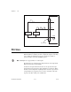
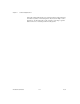
Connecting PFI Input Signals
All PFI input connections are referenced to D GND. Figure 10-3 shows this
reference, and how to connect an external PFI 0 source and an external
PFI 2 source to two PFI terminals.