
User's Manual

Chapter 4 Analog Input
© National Instruments Corporation 4-5 NI USB-621x User Manual
pairs that form differential input channels, refer to the I/O Connector Signal
Descriptions section of Chapter 3, Connector Information.
Caution The maximum input voltages rating of AI signals with respect to AI GND (and
for differential signals with respect to each other) are listed in the specifications document
for your device. Exceeding the maximum input voltage of AI signals distorts the
measurement results. Exceeding the maximum input voltage rating also can damage the
device and the computer. NI is not liable for any damage resulting from such signal
connections.
AI ground-reference setting is sometimes referred to as AI terminal
configuration.
Configuring AI Ground-Reference Settings in Software
You can program channels on an M Series device to acquire with different
ground references.
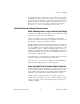
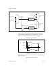
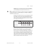
To enable multimode scanning in LabVIEW, use
NI-DAQmx Create
Virtual Channel.vi
of the NI-DAQmx API. You must use a new VI for
each channel or group of channels configured in a different input mode. In
Figure 4-3, channel 0 is configured in differential mode, and channel 1 is
configured in RSE mode.
Figure 4-3. Enabling Multimode Scanning in LabVIEW
To configure the input mode of your voltage measurement using the DAQ
Assistant, use the Terminal Configuration drop-down list. Refer to the
DAQ Assistant Help for more information about the DAQ Assistant.
To configure the input mode of your voltage measurement using the
NI-DAQmx C API, set the terminalConfig property. Refer to the
NI-DAQmx C Reference Help for more information.