VXI VXI-USB User Manual VXI-USB User Manual December 2004 371381A-01
Support Worldwide Technical Support and Product Information ni.
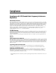
Important Information Warranty The VXI-USB is warranted against defects in materials and workmanship for a period of one year from the date of shipment, as evidenced by receipts or other documentation. National Instruments will, at its option, repair or replace equipment that proves to be defective during the warranty period. This warranty includes parts and labor.
Compliance Compliance with FCC/Canada Radio Frequency Interference Regulations Determining FCC Class The Federal Communications Commission (FCC) has rules to protect wireless communications from interference. The FCC places digital electronics into two classes. These classes are known as Class A (for use in industrial-commercial locations only) or Class B (for use in residential or commercial locations). All National Instruments (NI) products are FCC Class A products.
Contents About This Manual Conventions ...................................................................................................................vii Related Documentation..................................................................................................viii Chapter 1 Introduction What You Need to Get Started ......................................................................................1-1 VXI-USB Interface Kit Overview ........................................................
Contents Appendix A Specifications Appendix B Default Settings Appendix C Advanced Hardware Configuration Settings Appendix D Common Questions Appendix E Technical Support and Professional Services Glossary Index VXI-USB User Manual vi ni.
About This Manual This manual contains instructions for installing and configuring the VXI-USB interface kit. It also discusses how to start developing your VXI/VME application. Conventions The following conventions appear in this manual: » The » symbol leads you through nested menu items and dialog box options to a final action. The sequence File»Page Setup»Options directs you to pull down the File menu, select the Page Setup item, and select Options from the last dialog box.
About This Manual Related Documentation The following documents contain information that you might find helpful as you read this manual: VXI-USB User Manual • ANSI/IEEE Standard 1014-1987, IEEE Standard for a Versatile Backplane Bus: VMEbus • ANSI/IEEE Standard 1155-1998, IEEE VMEbus Extensions for Instrumentation: VXIbus • ANSI/VITA 1-1994, VME64 • Universal Serial Bus Specification, Revision 2.0 • VXI-6, VXIbus Mainframe Extender Specification, Rev. 2.
1 Introduction This chapter describes your VXI-USB interface kit, lists what you need to get started, and includes a brief description of the hardware and software. The VXI-USB interface kit links a PC-based computer to the VXIbus using the Universal Serial Bus (USB). This kit makes your computer perform as if it were plugged directly into the VXI backplane, giving your external computer the capability of an embedded computer. USB 2.
Chapter 1 Introduction VXI-USB Interface Kit Overview The interface kit described in this manual links a USB-equipped computer directly to the VXIbus using USB 2.0. The VXI-USB kit uses this high-speed (480 Mbps) serial bus to link your computer running Windows to a VXI chassis. You can use the VXI-USB kit with USB 1.0, but performance will be significantly slower than with USB 2.0 for many types of operations. Note You can connect multiple USB devices to the host.
Chapter 1 Introduction The VXI-USB links the computer to the VXIbus and converts USB data transfers into VXIbus data transfers and vice versa. The VXI-USB includes additional USB Series A ports you can use to connect other USB devices. VXI-USB Front Panel Features The VXI-USB has the following front panel features: • Front panel LEDs – FAILED—Indicates the VXI-USB is asserting SYSFAIL on the bus due to a controller failure.
Chapter 1 Introduction Advanced Configuration Options The VXI-USB default hardware configuration should be acceptable for most systems. Refer to Appendix B, Default Settings, only if your system uses the front-panel CLK10 and trigger SMB connectors.
Chapter 1 Introduction extensive libraries of VXI instrument drivers written to take full advantage of direct VXI control. LabVIEW, Measurement Studio, and LabWindows/CVI include all the tools needed for instrument control, data acquisition, analysis, and presentation. LabVIEW is an easy-to-use, graphical programming environment you can use to acquire data from thousands of different instruments, including IEEE 488.2 devices, VXI devices, serial devices, PLCs, and plug-in data acquisition boards.
Installation and Configuration 2 This chapter explains how to set up your test system. Installing the Software Use the Setup program that came with your NI-VXI/NI-VISA software to install the entire software package or a software update, or to reinstall software in the event that your files were accidentally erased. Some of the utilities rely on the LabWindows/CVI Run-Time Engine. This software is installed, if necessary, during the NI-VXI/NI-VISA installation.
Chapter 2 Installation and Configuration To keep the manufacturer/model name tables or the VME device configuration from a previous installation, be sure to back them up before starting Setup. They are in the TBL subdirectory of your NI-VXI directory, usually Program Files\National Instruments\VXI. Caution Setup is an interactive, self-guiding program that installs the NI-VXI and NI-VISA software and configures your system to use the software with the VXI-USB.
Chapter 2 Installation and Configuration restore them to the TBL subdirectory of your NI-VXI directory before running MAX. Note If you save and restore the TBL files from an older version of NI-VXI, the software will use TBL files that do not have the latest updates from National Instruments and may not include recent hardware releases.
Chapter 2 Installation and Configuration For information about the software, including optional settings, use MAX and its online help. Use the Windows Start menu to open the program group for National Instruments, launch MAX, and select Help»Help Topics. Installing the Hardware This section summarizes how to install your VXI-USB hardware. Your kit contains a VXI-USB interface module.
Chapter 2 Installation and Configuration Installing Your VXI-USB Interface Module All kits contain a VXI-USB interface module. To install the VXI-USB in Slot 0 of your VXI chassis, complete the following steps: 1. Power off the chassis. 2. Verify that the backplane connector is intact and that there are no bent or missing pins on the module. 3. Insert the VXI-USB into the chassis in Slot 0, as shown in Figure 2-2. 4. Power on the chassis.
Chapter 2 Installation and Configuration performance. Plug-in boards with USB 2.0 ports are also supported but may not provide the highest performance. Full-speed (USB 1.x) ports are supported as well, but provide much lower performance. The LINK light (refer to Chapter 1, Introduction) on the front panel of your VXI-USB controller indicates your connection speed. Software Configuration and Verification To configure the software and verify the configuration, follow these steps: 1. Run MAX.
Developing Your Application 3 This chapter discusses the software utilities you can use to start developing applications that use NI-VXI. After installing the NI-VXI software, you can begin developing your VXI/VME application. Be sure to check the release notes for the latest application development notes and changes. NI-VXI, NI-VISA, and Related Terms Before you develop your application, it is important to understand the difference between NI-VXI, NI-VISA, and similar terms.
Chapter 3 Developing Your Application provide a high level of performance; however, there may be some slight changes in behavior for certain applications. Your software features several system development utilities including MAX, Resman, NI Spy, VISA Interactive Control (VISAIC), and optionally VXI Interactive Control (VIC). You can also access online help and a variety of examples to learn how to use NI-VXI for certain tasks.
Chapter 3 Developing Your Application Resman reports to MAX all errors it finds in your system. When you view your VXI system in MAX, you can easily spot any errors that Resman found while configuring the system. Figure 3-1. Right-Click a VXI System in MAX to Run Resman on that System After Resman detects and configures all your VXI/VME devices, you can use MAX to view specific information about each device in your system.
Chapter 3 Developing Your Application launch VISAIC (or VIC) from the Tools menu in MAX or from the VISA or VXI subgroups in Start»Programs»National Instruments. Try the following in VISAIC: In the tree view, navigate using your mouse to the VISA resource for your controller—probably VXI0::0::INSTR, representing the VXI system 0, logical address 0 instrument resource, as shown in Figure 3-2. Figure 3-2. Select Your Controller in VISAIC Open the selected resource and navigate to the Register I/O tab.
Chapter 3 Developing Your Application Figure 3-3. Successful viIn Access in the VISAIC Register I/O Tab (This Window May Look Slightly Different for LabVIEW Users) If the data value ends in FF6, you have successfully read the National Instruments manufacturer ID from your VXI/VME controller’s ID register. You may now want to read the configuration registers from other VXI devices in your system by opening the devices in VISAIC.
Chapter 3 Developing Your Application Older programs that use the NI-VXI API now use the NI-VXI-to-NI-VISA compatibility layer to communicate with the VXI devices. Using this layer, older programs can run in NI-VXI 3.0 or later without being rewritten to use the VISA interface. The NI-VXI API development environment is not installed by default as part of the NI-VXI installation.
Chapter 3 Developing Your Application Table 3-1. NI-VISA/NI-VXI Examples Coverage NI-VISA Example NI-VXI Example (Optional) Message-Based Access General\RdWrt.c VXIws.c High-Level Register Access VXI-VME\HighReg.c VXIhigh.c Low-Level Register Access VXI-VME\LowReg.c VXIlow.c VXI-VME\AsyncIntr.c VXIint.c Interrupt Handling and WaitIntr.c Trigger Handling VXI-VME\WaitTrig.c VXItrig.
Chapter 3 Developing Your Application NI-VXI API Notes The following notes apply only if you are using the NI-VXI API. We recommend that all new VXI/VME applications use the NI-VISA API, but you can still develop with the older NI-VXI API for compatibility with legacy code. Compiler Symbols You may need to define certain compiler symbols so that the NI-VXI library can work properly with your program.
Chapter 3 Developing Your Application are receiving triggers on an external controller, you may need to modify the trigger configuration on your extender module using MAX. In general, interrupts are routed automatically based on the interrupt configuration the resource manager detects. Whether the changed routing behavior affects your program is application dependent.
Chapter 3 Developing Your Application Figure 3-4. NI Spy VISAIC, discussed in the Device Interaction section, is an excellent platform for quickly testing instruments and learning how to communicate with them. Figure 3-5. VISAIC VXI-USB User Manual 3-10 ni.
A Specifications This appendix lists the specifications for the VXI-USB module. Requirements VXIbus configuration space................... 64 B Default.................................................... None Environmental Maximum altitude .................................. 2,000 m Pollution Degree .................................... 2 Indoor use only Operating Environment Ambient temperature range.................... 0 to 55 °C (Tested in accordance with IEC-60068-2-1 and IEC-60068-2-2.
Appendix A Specifications Shock and Vibration Operational shock ...................................30 g peak, half-sine, 11 ms pulse (Tested in accordance with IEC-60068-2-27. Test profile developed in accordance with MIL-PRF-28800F.) Random vibration Operating .........................................5 to 500 Hz, 0.3 grms Nonoperating ...................................5 to 500 Hz, 2.4 grms (Tested in accordance with IEC-60068-2-64.
Appendix A Specifications Slot requirements ................................... Single VXI C-size slot Compatibility ......................................... Fully compatible with VXI specification VXI keying class.................................... Class 1 TTL MTBF..................................................... Contact factory USB Capability Description USB 2.0, backward compatible with USB 1.1 host and devices.
Appendix A Specifications CE Compliance This product meets the essential requirements of applicable European Directives, as amended for CE marking, as follows: Low-Voltage Directive (safety)..............73/23/EEC Electromagnetic Compatibility Directive (EMC) .....................................89/336/EEC Refer to the Declaration of Conformity (DoC) for this product for any additional regulatory compliance information. To obtain the DoC for this product, visit ni.
Appendix A Specifications RETRY (master) VMEbus master retry support RETRY (slave) VMEbus slave retry support FSD First slot detector SCON VMEbus System Controller (Automatic Detection) PRI, RRS Prioritized or Round Robin Select arbiter ROR, FAIR Release on Request and FAIR bus requester IH(7-1) Interrupt handler for levels 7–1 I(7-1) Interrupt requester for levels 7–1 D32, D16, D08(O) (Interrupt Handler) VMEbus D32, D16, D08(O) interrupt handler D32, D16, D08(O) (Interrupter) VMEbus D32, D16, D08(O) inte
B Default Settings This appendix summarizes the default settings for the hardware and software in the VXI-USB kit. If you need more information about a particular setting or want to try a different configuration, refer to Appendix C, Advanced Hardware Configuration Settings, for your hardware reference and to the MAX online help for your software reference. Default Hardware Settings Figure B-1 and Table B-1 show the factory-default settings of the user-configurable switches on the VXI-USB.
Appendix B Default Settings Y N S1 ON ON OUT Inverted OFF OFF IN Noninverted S3 S4 S5 From Onboard Oscillator From SMB CLK10 In S2 S6 Figure B-1. VXI-USB Default Configuration Settings VXI-USB User Manual B-2 ni.
Appendix B Default Settings Table B-1. VXI-USB Hardware Default Settings Hardware Component Default Setting S1—Firmware recovery N: do not recover firmware S2—VXIbus CLK10 source From onboard oscillator S3—SMB trigger in termination ON: terminated S4—SMB CLK10 in termination ON: terminated S5—SMB CLK10 direction IN: receive CLK10 signal S6—SMB CLK10 out polarity Noninverted Default Software Settings Table B-2.
Advanced Hardware Configuration Settings C This appendix describes the alternate hardware configuration settings of the VXI-USB. The board is set at the factory for the most commonly used configuration. Use this appendix if you want to try a different hardware configuration or if you would like more information on a particular setting. This information is intended for more advanced users. The following hardware configuration settings are user configurable.
Appendix C Advanced Hardware Configuration Settings Y Y N N S1 S1 A. Boot from Onboard EEPROM and Flash Memory (Default) B. Boot from Firmware Image Stored on Host Figure C-1. Firmware Recovery Operation VXIbus CLK10 Routing The VXI-USB has four hardware switches that work together to control various aspects of CLK10 routing. Read this section carefully and notice that if you change one switch, you may need to change another.
Appendix C Advanced Hardware Configuration Settings When switch S5 is set so that the VXI-USB receives the SMB CLK10 signal, you have the option to add a 50 Ω termination to the signal by setting switch S4. S4 is unused when S5 is configured to drive the external CLK SMB signal. Table C-1 summarizes the most common configuration types. Table C-1.
Appendix C Advanced Hardware Configuration Settings From Onboard Oscillator From SMB CLK10 In S1 S2 ON OUT Inverted OFF IN Noninverted S4 S3 S5 S6 Figure C-2. Default Settings for CLK10 Switches In Figures C-3 and C-4, switch S2 uses the alternate configuration to generate the VXIbus CLK10 signal. Instead of the onboard oscillator, the VXI-USB generates from the external CLK SMB connector and drives to the backplane. You can choose whether to terminate the signal using S4.
Appendix C Advanced Hardware Configuration Settings From Onboard Oscillator From SMB CLK10 In S1 S2 ON OUT OFF IN S4 S3 S5 S6 Figure C-4. Receive External CLK SMB with 50 Ω Termination and Drive to the Backplane Figures C-5 and C-6 show two configurations for driving the external CLK SMB from the VXIbus CLK10 signal by changing switch S5 to its alternate setting. Switch S2 must be in its default position for these configurations.
Appendix C Advanced Hardware Configuration Settings From Onboard Oscillator From SMB CLK10 In S1 S2 S4 S3 OUT Inverted IN Noninverted S5 S6 Figure C-6. Drive Noninverted External CLK SMB Trigger Input Termination Located within the group of CLK10 switches is switch S3, which controls whether to put a 50 Ω termination on the external trigger input SMB. Figure C-7 shows the setting for a nonterminated trigger input SMB. Use the default setting of Figure C-7B to terminate the trigger input SMB.
D Common Questions This appendix addresses common questions you may have about using the NI-VISA/NI-VXI software on the VXI-USB platform. What does hot plugging mean in terms of USB? The concept of hot plugging in USB means that you can remove and insert USB cables without powering down your computer and devices. The USB Plug and Play architecture is designed so that the host computer can recognize when to load and remove the appropriate drivers.
Appendix D Common Questions How can I determine the serial number and firmware version of the VXI-USB module? This information is displayed in the title bar of the Hardware Configuration window in MAX. What is Resman? Resman is the utility that performs the duties of a VXI Resource Manager as discussed in the VXIbus specification. When you set a National Instruments controller to Logical Address 0, you will at some point need to run Resman to configure your VXI instruments.
Appendix D Common Questions What can I do to make sure that my system is up and running? The fastest method for testing the system is to run Resman. This program attempts to access memory in the upper A16 address space of each device in the system. If Resman does not report any problems, the VXI-USB communication system is operational. To test individual devices, you can use the VIC or VISAIC program to interactively issue NI-VXI functions or NI-VISA operations, respectively.
Appendix D Common Questions When all LEDs except the SYSFAIL LED are on, the hardware detected that the FPGA PLL lost lock, and the board may be in an unstable state. Power cycle the board to repair it. In an empty chassis, when both the SYSFAIL and FAIL LEDs are solid on, the firmware image is corrupted. Recover the firmware to repair the board. What kind of signal is CLK10 and what kind of signal do I need for an external CLK10? CLK10 is a differential ECL signal on the VXIbus backplane.
Technical Support and Professional Services E Visit the following sections of the National Instruments Web site at ni.com for technical support and professional services: • Support—Online technical support resources at ni.
Glossary Symbol Prefix Value p pico 10 –12 n nano 10 –9 µ micro 10 – 6 m milli 10 –3 k kilo 10 3 M mega 10 6 G giga 10 9 T tera 10 12 Symbols ° degrees Ω ohms A A amperes address Character code that identifies a specific location (or series of locations) in memory. In VISA, it identifies a resource. address modifier One of six signals in the VMEbus specification used by VMEbus masters to indicate the address space in which a data transfer is to take place.
Glossary ANSI American National Standards Institute API Application Programming Interface—the direct interface that an end user sees when creating an application. arbitration A process in which a potential bus master gains control over a particular bus. B B Byte—eight related bits of data, an 8-bit binary number. Also used to denote the amount of memory required to store one byte of data.
Glossary byte order How bytes are arranged within a word or how words are arranged within a longword. Motorola ordering stores the most significant byte (MSB) or word first, followed by the least significant byte (LSB) or word. Intel ordering stores the LSB or word first, followed by the MSB or word.
Glossary dynamically configured device A device that has its logical address assigned by the Resource Manager. A VXI device initially responds at Logical Address 255 when its MODID line is asserted. The Resource Manager subsequently assigns it a new logical address, to which the device responds until powered down. E ECL Emitter-Coupled Logic EEPROM Electronically Erasable Programmable Read Only Memory—ROM that can be erased with an electrical signal and reprogrammed.
Glossary H hex Hexadecimal—the numbering system with base 16, using the digits 0 to 9 and letters A to F. Hz hertz; cycles per second I I/O Input/output—the techniques, media, and devices used to achieve communication between machines and users. IEC International Electrotechnical Commission. The IEC publishes internationally recognized standards. IEC 60068 contains information on environmental testing procedures and severities. IEEE Institute of Electrical and Electronics Engineers in.
Glossary L logical address An 8-bit number that uniquely identifies each VXIbus device in a system. It defines the A16 register address of a device, and indicates Commander and Servant relationships. M m meters M mega—(1) the standard metric prefix for 1 million or 106, when used with units of measure such as volts and hertz; (2) the prefix for 1,048,576, or 220, when used with B (byte) to quantify data or computer memory.
Glossary NI-VXI The National Instruments bus interface software for VME/VXIbus systems. Non-Slot 0 device A device configured for installation in any slot in a VXIbus mainframe other than Slot 0. Installing such a device into Slot 0 can damage the device, the VXIbus backplane, or both. P PCI Peripheral Component Interconnect. The PCI bus is a high-performance 32-bit or 64-bit bus with multiplexed address and data lines.
Glossary Slot 0 device A device configured for installation in Slot 0 of a VXIbus mainframe. This device is unique in the VXIbus system in that it performs the VXI/VMEbus System Controller functions, including clock sourcing and arbitration for data transfers across the backplane. Installing such a device into any other slot can damage the device, the VXIbus backplane, or both. SMB Sub Miniature Type B connector that features a snap coupling for fast connection.
Glossary VME Versa Module Eurocard or IEEE 1014 VMEbus System Controller A device configured for installation in Slot 0 or a VXIbus mainframe or the first slot in a VMEbus chassis. This device is unique in the VMEbus system in that it performs the VMEbus System Controller functions, including clock sourcing and arbitration for data transfers across the backplane. Installing such a device into any other slot can damage the device, the VMEbus/VXIbus backplane, or both.
Index A D advanced configuration options, 1-4 advanced hardware configuration settings, C-1 application development, 3-1 configuration, 3-2 debugging, 3-9 device interaction, 3-3 NI-VXI API notes, 3-8 optimizing large VXIbus transfers, 3-7 programming for VXI, 3-5 debugging, 3-9 default configuration settings, B-1 default settings hardware, B-1 software, B-3 developing applications, 3-1 device interaction, 3-3 device tab default settings (table), B-3 diagnostic tools (NI resources), E-1 documentation con
Index NI-VISA, 1-4, 3-1 examples (table), 3-7 installation, 2-1 NI-VXI, 1-4, 3-1 compatibility layer, 3-1 examples (table), 3-7 installation, 2-1 utility programs using to configure VXI-USB, D-2 using to perform startup Resource Manager operations, D-2 NI-VXI API, 3-1 compatibility layer options, 3-8 compiler symbols, 3-8 notes, 3-8 default settings, B-1 description, 1-2 determining revision, D-2 installation, 2-4 help, technical support, E-1 hot plugging, D-1 I installation, 2-1 hardware, 2-4 software,
Index S V safety specifications, A-3 selecting controller in VISAIC (figure), 3-4 serial number, determining, D-2 shock and vibration specifications, A-2 software configuration, 2-6 installation, 2-1 completing, 2-2 verification, 2-6 software (NI resources), E-1 specifications, A-1 CE compliance, A-4 cleaning, A-4 electromagnetic compatibility, A-3 environmental, A-1 physical, A-2 power requirement, A-2 requirements, A-1 safety, A-3 shock and vibration, A-2 USB compatibility description, A-3 VMEbus capab
Index kit overview, 1-2 software configuration and verification, 2-6 installation, 2-1 specifications, A-1 W Web resources, E-1 VXI-USB User Manual I-4 ni.