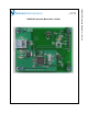
LM95235 Evaluation Board User’s Guide © Copyright 2006 National Semiconductor Corporation 1 www.national.
LM95235 Evaluation Board User’s Guide Table of Contents Table of Contents 2 References 3 1.0 Introduction 4 2.0 Quick Start 5 3.0 Functional Description 7 4.0 Software Installation and Operation 8 5.0 Electrical and Mechanical Specifications 9 5.1 Electrical Specifications 9 5.2 Electrical Schematic 9 5.3 Evaluation Board Layout 10 5.4 Bill of Materials 11 5.5 Mechanical Specifications 11 © Copyright 2006 National Semiconductor Corporation 2 www.national.
LM95235 Evaluation Board User’s Guide References 1. “LM95235 Precision Remote Diode Temperature Sensor With SMBus Interface and TruTherm™ Technology” datasheet. The latest copy of the LM95235 datasheet can be obtained by going to the National Semiconductor website www.national.com, by searching on “LM95235”, and then downloading the LM95235.pdf file. 2. SensorEval Version 1.1.0a or later, Evaluation Board CD containing: a. The SensorEval.exe executable program used to run the LM95235 Evaluation Board. b.
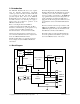
1.0 Introduction The LM95235 Evaluation Board is used together with the National Semiconductor SensorEval software (provided in the kit), and with a USB cable (not provided in the kit), and with an external personal computer (PC). Power to the LM95235 Evaluation Board is provided by the +5 VDC line of the USB connection. No external power supply or signal sources are required for operation of the LM95235 evaluation board. The block diagram below describes the LM95235 Evaluation Board itself.
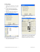
2.0 Quick Start 1. Install the CD into the CD drive of the computer and install the SensorEval software (see Section 4.0). 2. Hookup the USB cable between the PC or 3. notebook computer and the LM95235EVAL board as shown in Quick Start Diagram (See Section 2.1). Run the SensorEval software clicking the icon on the desktop. The first screen after the installation will look like this: Select the LM95235 Evaluation Board. Click OK. 5. The next screen will look like this: If not, select “Another Device”.
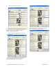
. The Screen should look like this: . The user can also select the 3904 diode or the processor thermal diode called “90 nm”. Local (on-chip) and remote temperatures should read continuously. The user can experiment with the different settings of Address BF. 7. If the user clicks the 06-FF tab the next screen will look like this: The user can experiment with the Mask settings. Also the user can change the conversion rate. The next screen shows the possibilities for the Conversion Rate.
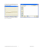
8. If the user clicks on the Start Plot button a graph box will appear and will graph the temperature. An example is shown below 9. If the user selects the Start Log button the following screen will appear. The user then enters the filename that he chooses to log the data into. © Copyright 2006 National Semiconductor Corporation 7 www.national.
2.1 Quick Start Diagram Important! NO EXTERNAL POWER SUPPLY OR SIGNAL INPUTS ARE REQUIRED! N/C TCRIT# N/C OS/A0 SCL SDA LM95235 +3.3 JP2 USB Cable to Computer Computer with SensorEval software loaded National Semiconductor LM95235 Evaluation Board Rev. 1 © Copyright 2006 National Semiconductor Corporation 8 www.national.
Power to the LM95235 Evaluation Board is taken from the USB 5-Volt line. This +5 VDC is the input to the on-board LM2950 low dropout voltage regulator, which regulates the output voltage to +3.3 VDC. This output voltage powers the LM95235, the on-board microcontroller, and the EEPROM chip where the board ID information is stored. 3.
4.0 Software Installation and Operation 4.1 Installation 4.2 Operation The CD provided in the LM95235 Evaluation Board Kit contains the SensorEval software used to make the LM95235 Evaluation Board operate with the user’s PC. It is assumed that the user will be using a PC with a Pentium® III or higher processor and Microsoft Windows® XP/2000/98/ME operating system. Follow the following procedure for operation the LM95235 Evaluation Board using the SensorEval software: 1.
5.0 Electrical and Mechanical Specifications 5.1 Electrical Specifications Power Requirements The Board uses the +5.0 VDC and GND lines from the USB connection. +5.0 ± 0.1 V, This +5.0 VDC voltage is regulated down to +3.3 VDC for board power. 100 mA max. * NO EXTERNAL POWER SUPPLY INPUTS ARE REQUIRED * 5.2 Electrical Schematic + 3.3 VDC C1 0.1uF C2 0.1uF TP1 Use a 0.1 uF capacitor for each Vcc pin of U2 and Reserved_6 pin. C3 0.1uF C4 0.1uF C5 0.1uF + 3.3 VDC C6 0.1uF GND R1 0 + 3.
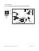
5.3 Evaluation Board Layout Figure 5.3 Layout diagram of the LM95235 Evaluation Board (Note: socket and socket area not stuffed.) © Copyright 2006 National Semiconductor Corporation 12 www.national.
5.4 Bill of Materials for LM95235 Evaluation Board Item Qty Reference Part PCB Footprint 1 11 Capacitor, SMD, ceramic, 0.1uF sm/c_0805 2 3 4 5 6 7 8 9 10 11 12 13 14 15 16 17 18 2 3 2 1 1 1 1 1 2 2 5 1 1 1 1 1 1 C1,C2,C3,C4,C5,C6, C12,C15,C17,C20 C9, C10 C11,C14,C16 C13,C19 J3 J4 L1 Q1 R1 R4,R12 R7,R9 R2,R11,R13,R14,R15 R3 U1 U2 U4 U3 Y1 Capacitor, SMD, ceramic, 33 pF Capacitor, SMD, ceramic, 2.
5.4 Mechanical Specifications 5.4.1 Operating Mechanical and Environmental Specifications Temperature Minimum 0°C Typical 25°C Maximum 70°C 5.4.2 Evaluation Board Basic Dimensions 2.45 in/6.22 cm 3.25 in/8.76 cm 5.4.3 Electrostatic Discharge (ESD) Precautions The user shall use ESD precautions as specified in National Semiconductor ESD control document (SC)CSI-3-038 available through www.national.com. © Copyright 2006 National Semiconductor Corporation 14 www.national.
BY USING THIS PRODUCT, YOU ARE AGREEING TO BE BOUND BY THE TERMS AND CONDITIONS OF NATIONAL SEMICONDUCTOR'S END USER LICENSE AGREEMENT. DO NOT USE THIS PRODUCT UNTIL YOU HAVE READ AND AGREED TO THE TERMS AND CONDITIONS OF THAT AGREEMENT. IF YOU DO NOT AGREE WITH THEM, CONTACT THE VENDOR WITHIN TEN (10) DAYS OF RECEIPT FOR INSTRUCTIONS ON RETURN OF THE UNUSED PRODUCT FOR A REFUND OF THE PURCHASE PRICE PAID, IF ANY.