
Installation Guide


Operating Instructions
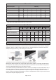
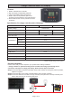
Model
Battery Voltage
Cut-in Voltage
Cut-out Voltage
Max Input Charge Current
60011 60012
12V Only
13V
14.2V
11A 12A
Observe manufacturer’s safety procedures when working around batteries and other electrical
equipment.
Always connect charge controller to the battery first and remove last.
This product is designed to be used on 12 volt configurations in parallel,
*Optional 2x6 volt in series.
*Optional 24 volt while using controller with LCD display as shown in this manual.
This product is designed to receive charges from 12 Volt Solar Panels.
This product should be placed in a well ventilated dry area, free from flammable gases, weather, and
moister. Charge controller is NOT weatherproof.
Charge controller should not be installed further than 2 to 5 ft. way from the battery. Solar Panel
distance must not reach further than 20 ft way from battery or loss of current may occur.
LED light indicates a full battery charge "green" at 14.2 Volts, at this time the charge controller will cut out
to prevent overcharging.
LED light indicates battery charging "yellow" when battery reaches below 13 Volts, charge controller will
cut in and allow solar panel to being charging.
23
1
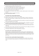
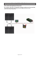
Electrical Installation
Please confirm that you have all parts to your system before starting installation.
* Charge controller is optional and may not be included. below image just showing how to
connect the solar panel to charge your battery. Reverse below steps to uninstall.
Step1 Connect the battery with SAE-battery clamp cable, Always connecting the postive to positive,
negative to negative.
Step2 Connect the SAE connector to charge controller (battery side of charge controller)
Step3 Connect the solar panel to charge controller (solar panel side of charge controller)
Page 6 of 12
Charge Controller With Indicate Light
Specification