
Installation Guide


Page 7 of 12
23
1
Features
1. Build-in industrial micro controller.
2. Big LCD display. all adjustable parameter.
3. Fully 4-stage PWM charge management.
4. Build-in short-circuit protection,open-circuit
protection,reverse protection.over-load protection.
5. Dual mosfet Reverse current protection,low heat
production.
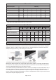
MODEL
Battery Voltage
Max Input Charge Current
Max Discharge Current
Max Solar Input
Equalization
*
Float Charge Voltage*
13.7V (Default, Adjustable)
10.7V (Default, Adjustable)
12.6V (Default, Adjustable)
5V/3A
<10mA
-35~+60℃
150*78*35mm / 150g
LVD(Low Voltage Disconnect)
*
LVR(Low Voltage Recovery)*
USB Output
Self-Consume
Operation Temperature
Size / Weight
NPCC11 NPCC13 NPCC20
11A 13A 20A
11A 13A
<50V
12V/24V Auto
20A
B01 Sealed
B02 Gel
B03 Flood
14.4V
14.2V
14.6V
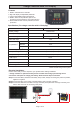
Specification ( For charge controller with LCD display)
*Value x2 while using in 24V system
Charge Controller With LCD Display
Electrical Installation
Please confirm that you have all parts to your system before starting installation.
* Charge controller is optional and may not be included. below image just showing how to
connect the solar panel to charge your battery. Reverse below steps to uninstall.
Step1 Connect the battery with Bare end-battery clamp cable, Always connecting the postive to positive,
negative to negative.
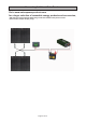
Step2 Connect the bare end to charge controller (battery side of charge controller)
Step3 Connect the SAE-bare end cable to charge controller (solar panel side of charge controller), and
use the SAE connector to connecting solar panel.
DC Output