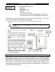
INSTALLATION AND OPERATING INSTRUCTIONS MANUAL TRANSFER SWITCHES FROM 0
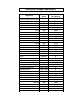
Residential Wattage Requirements Running Watts Add watts for starting 300 500 500 600 700 875 500 750 750 1000 1400 2100 750 1000 1400 2350 800 1050 800 1300 2150 2300 550 750 on bulb 50-200 100-300 600-1500 1750 1050-1850 1100-1500 650-800 400 1150 700 1100 1400 0 0 0 0 0 0 0 0 0 2300 1800 700 1450 800-1100 300-1500 1200 1400 1400 0 0 0 Appliance Furnace blower, gas or fuel 1/8 hp 1/8 hp 1/6 hp 1/4 hp 1/3 hp 1/2 hp Shallow well pump 1/3 hp 1/2 hp Sump pump 1/3 hp 1/2 hp Refrigerator or freezer
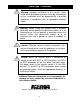
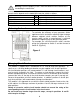
Warnings • Cautions Warning: Improper installation of this transfer switch could cause damage or personal injury by electrocution or fire. Installation must be performed by a qualified electrician in compliance with all applicable electrical codes Warning: When using this product with a portable generator, do not operate the generator indoors or in an enclosed area. Do not operate a generator where the exhaust fumes can accumulate indoors or in an enclosed area like a garage or close to windows or doors.
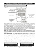
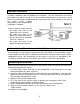
Reliance Installation and Operating Instructions Key Components of the Reliance Transfer Switch Figure 1 Circuit breakers. Each transfer switch circuit has a 1-in interchangeable circuit breaker that protects the branch circuit when the circuit selector switch is in the GEN position. In the LINE position, each branch circuit is protected by the breaker in the load center. Circuit selector switches.
Installation Instructions Preparing for Installation You will need the following items: Electric drill Screwdriver Wire cutters/stripper Hammer Four anchors and screws 6 or 10 yellow wire connectors (depending on the model) 4 red wire connectors for the 20A and 30A hard-wire models The following five steps generally apply to all transfer switch installations. The transfer switch may be installed on either side of the load center. 1.
Warning: Failure to properly install a multi-wire branch circuit could result in overloading the neutral wire. The maximum number of circuits available and those that can be used for multi-wire branch circuits depends on the model of the transfer switch as follows: Available for multi-wire branch circuits Model Max Circ A304 4 Any two adjacent circuits. A306, A506 6 Any two adjacent circuits. A308 8 Any two adjacent circuits. A310, A510 10 Any two adjacent circuits.
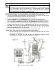
Installing 120-volt Circuits Warning: Transfer switch circuits with 20 amp breakers must be installed on only those branch circuits with 20 amp branch circuit breakers. Transfer switch circuits with 15 amp breakers can be installed on 15 or 20 amp branch circuits. Do not install any transfer switch circuit on branch circuits greater than 20 amps, except in position A and B which maybe 30 amps. Wire the most critical circuits first, starting with any circuit position on the transfer switch.
Installing 240-volt Circuits Any two adjacent circuit selector switches may be used for a double-pole 240-volt circuit. Use a handle tie to connect the two circuit selector switches. *Note: Circuits used for multi-wire branch circuits are not available for 240-volt circuits Removing handle tie(s). If there are no 240-volt or multi-wire circuits in the transfer switch installation, handle-ties on the switches are not needed.
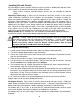
Hard-wire Installation "Hard-wire" installation to a power inlet box located remotely from the transfer switch (Figure 5) requires additional steps to complete the installation. The wire connections to the wires from power inlet box are made in the circuit breaker compartment of the transfer switch. Access the circuit breaker compartment by removing the two screws located on the sides of the lower circuit breaker compartment cover. Replace when installation is complete.
Operating Instructions Using your Reliance Transfer Switch and Your Portable Generator Warning: Do not operate a generator in an enclosed area. Do not operate a generator where the exhaust fumes can accumulate in an enclosed area. You want your generator to be ready when you need it. Therefore, it is important to perform the following steps at least once a month to keep the generator in peak running condition. • Start and run your generator under load regularly. • Keep the fuel tank filled with fresh fuel.
Transferring from Generator Power to Utility Power 1. Return all circuit selector switches to the LINE position. 2. Follow the procedures in the generator owner's manual to turn off the generator. 3. Unplug the power cord. Notes on Models Without Watt Meters Check the nameplate on each appliance or motor and note the load for each. Determine the total running wattage of your generator.
Transfer Switch Parts List 3 Description Circuit breaker, 15 A S.P. Circuit breaker, 20 A S.P. Circuit breaker, 20 A D.P. Circuit breaker, 30 A D.P. Wattmeter, 20 / 30 A Wattmeter, 50 / 60 A Current Transformer (C.T.