Nautilus™ U618 Upright Bike Service Manual ™ ™ Service Manual 8012455.101518.
™ ™ Important Safety Instructions and General Troubleshooting Information for the Nautilus™ U618 Bike Service Procedures 8012569.101518.B NOTICE: This document provides important safety instructions, adjustments, and general troubleshooting information for the maintenance of the Nautilus™ U618 Upright Bike. If you need assistance, please contact Customer Service (if purchased in US/Canada) or your local distributor (if purchased outside US/Canada). To find your local distributor, go to: www.
Safety Warning Labels and Serial Number WARNING! • Injury or death is possible if caution is not used while using this machine. • Keep children and pets away. • Read and follow all warnings on this machine. • Refer to the Owner’s Manual for additional warnings and safety information. • The heart rate displayed is an approximation and should be used for reference only. • Not intended for use by anyone under 14 years of age. • The maximum user weight for this machine is 325 lbs ( 147 kg ).
Specifications Maximum User Weight: 147.4 kg (325 lbs.) Total Surface Area (footprint) of equipment: 5670 cm2 Machine Weight: 37.7 kg (83.1 lbs.) Power Requirements: Input Voltage: 100 - 240V AC, 50/60Hz Output Voltage: 9VDC, 1.5A Heart Rate Chest Strap: 1 CR2032 battery 148cm (58.3”) DO NOT dispose of this product as refuse. This product is to be recycled. For proper disposal of this product, please follow the prescribed methods at an approved waste center. 98cm (38.
Maintenance Read all maintenance instructions fully before you start any repair work. In some conditions, an assistant is necessary to do the necessary tasks. Equipment must be regularly examined for damage and repairs. The owner is responsible to make sure that regular maintenance is done. Worn or damaged components must be repaired or replaced immediately. Only manufacturer supplied components can be used to maintain and repair the equipment.
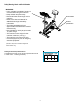
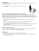
Moving the Bike To move the upright bike, carefully tilt the Handlebars toward you while pushing the front of the bike downward. Push the bike to the desired location. NOTICE: Be careful when you move the bike. Abrupt motions can affect the computer operation. Bluetooth® Connectivity with the “Nautilus Trainer™” Fitness App This fitness machine is equipped with Bluetooth® connectivity and can wirelessly sync with the “Nautilus Trainer™” Fitness App on supported devices.
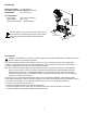
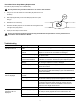
Heart Rate Chest Strap Battery Replacement The heart rate (HR) chest strap uses a CR2032 battery. ! Do not perform this procedure outdoors or in moist or wet locations. 1. Using a coin, loosen the slotted cover on the battery bay. Remove the cover and battery. CR2032 2. When replacing the battery, insert it in the battery bay with the + symbol facing up. 3. + Reinstall the cover on the strap. 4. Discard the old battery.
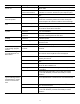
Condition/Problem Things to Check Solution Check User Profile Select the Edit User Profile option for the User Profile. Go to the WIRELESS HR setting and make sure that the current value is set to ON. Interference Try moving unit away from sources of interference (TV, Microwave, etc). Replace Chest Strap If interference is eliminated and HR does not function, replace strap. Replace Console If HR still does not function, replace Console.
Condition/Problem Things to Check Fan will not turn on or will not turn off Check data cable integrity All wires in cable should be intact. If any are cut or crimped, replace cable. Check data cable connections/orientation Be sure cable is connected securely and oriented properly. Small latch on connector should line up and snap into place. Reset machine Unplug unit from electrical outlet for 3 minutes. Reconnect to outlet.
Console Service Mode – x618 series Consoles The Console Setup Mode lets you input the date and time, set the units of measurement to either English or Metric, change the machine type, control the sound settings ( on/ off), or see maintenance statistics (Total Run Hours – for service technician use only). 1. To go into the Console Setup Mode: - For the later version of the console, hold down the PAUSE/END button and Increase () button together for 3 seconds while in the Power-Up Mode.
g. RUN LED TEST – Drives LEDs to the following states: 1. All LEDs On 1 second 2. All LEDs Off 1 second 3. Sequence Segments 1 at a time – on 1 second, off 1 second Press any key to exit test h. RUN LCD TEST – Drives 3x5 and 1x5 LCD displays with the following patterns: 1. All segments on 2. All segments off 3. Set individual segments one at a time until all segments are illuminated. Press any key to exit. i. RESET CONSOLE – Resets the data from user inputs.
Maintenance Parts Exploded View Your machine may differ. Use only as a guide.
REPLACEMENT PROCEDURE SKILL LEVEL Level I : Level II : Level III : ! Low - very little mechanical knowledge or exposure. Intermediate - some experience with mechanical procedures Advanced - knowledgeable about mechanical procedures Disconnect all power to the machine before you service it. When disposing of old parts, obey the applicable local and provincial requirements.
™ ™ Adjust the Belt Tension on the Nautilus™ U618 and R618 Bikes Replacement Procedure Skill Level: II 8012570.101518.B NOTICE: This document provides instructions for the adjustment of the Drive Belt tension on the Nautilus™ U618 Upright Bike and R618 Recumbent Bike. If you need assistance, please contact Customer Service (if purchased in US/Canada) or your local distributor (if purchased outside US/Canada). To find your local distributor, go to: www.nautilusinternational.
NOTICE: It is necessary to remove the Shrouds for this procedure. Refer to the “Replace the Shrouds” procedure. ! Disconnect all power to the machine before you service it. Note: Your machine may not match the image. For reference only. Figure 1 1. Remove the Top Shroud, Left Shroud and Right Shroud from the Main Unit. Refer to the “Replace the Shrouds” procedure. 2. To test the Drive Belt tension: • Push the Drive Belt downward at the midpoint (M) between the pulleys and measure the distance.
6. Reassembly is the reverse procedure. NOTICE: Be sure not to crimp any cables. 7. Final Inspection Inspect your machine to ensure that all hardware is tight and components are properly assembled. ! Do not use until the machine has been fully assembled and inspected for correct performance in accordance with the Owner’s Manual.
™ ™ Set the Brake Tension (Calibration) on the Nautilus™ U618 Bike Replacement Procedure Skill Level: III 8012571.101518.B NOTICE: This document provides instructions for the calibration of the Brake tension on the Nautilus™ U618 Upright Bike. If you need assistance, please contact Customer Service (if purchased in US/Canada) or your local distributor (if purchased outside US/Canada). To find your local distributor, go to: www.nautilusinternational.
NOTICE: It is necessary to remove the shrouds for this procedure. Refer to the “Replace the Shrouds” procedure. Note: Your machine may not match the image. For reference only. 1. Disconnect and reconnect the AC Adapter from the wall outlet to turn the power off and on. 2. Push QuickStart and verify that the console shows that the default resistance level is 4. isconnect all power and allow to sit for 5 D minutes. 3. Carefully remove the Seat Post, Left Shroud and Right Shroud.
7. To adjust the Brake tension, loosen the 2 hex head bolts (C) and move the Servo Motor assembly (D) until the closest point on the Brake Magnet (A) is within 3.0 mm (1/8”) of the Flywheel (B). Tighten the bolts. Note: I f the cardboard is not 3mm (1/8”) thick, you can use the pages of a paperback book to measure the gap. Approximately 36 pages (sheets) = 3mm. C A B D 8. Turn the power on again. Use the console to check the resistance adjustment. achine is on. Current is active.
™ ™ Replace the Console on the Nautilus™ U618 and R618 Bikes Replacement Procedure Skill Level: I 8012572.101518.B NOTICE: This document provides instructions for the replacement of the Console on the Nautilus™ U618 Upright Bike and R618 Recumbent Bike. If you need assistance, please contact Customer Service (if purchased in US/Canada) or your local distributor (if purchased outside US/Canada). To find your local distributor, go to: www.nautilusinternational.
Disconnect all power to the machine before you service it. Note: Your machine may not match the image. For reference only. 1. Press the edges of the Console Pivot Shroud to disengage the tabs from the Console. Remove the Console Pivot Shroud and set it safely aside. 2. Remove screws that attach Console to the Mast. Carefully lift the Console off the Mast. 3. Disconnect the Data Cable, Heart Rate Cable and Resistance Cable at the top of the Mast. Discard the Console and screws.
™ ™ Replace the Pedals on the Nautilus™ U618 and R618 Bikes Replacement Procedure Skill Level: I 8012573.101518.B NOTICE: This document provides instructions for the replacement of the Pedals on the Nautilus™ U618 Upright Bike and R618 Recumbent Bike. If you need assistance, please contact Customer Service (if purchased in US/Canada) or your local distributor (if purchased outside US/Canada). To find your local distributor, go to: www.nautilusinternational.
Note: Your machine may not match the image. For reference only. 1. Loosen and remove the old Pedals. Discard the old Pedals. Note: The Left Pedal is reverse-threaded. Orientation is based from a seated position on the bike. The Left Pedal has an “L”, the Right Pedal an “R”. (R) (L) 2. Install the new Pedals. Carefully align the threads and hand tighten to prevent cross-threading. Then tighten fully with pedal wrench. Note: T he Left Pedal is reverse-threaded.
™ ™ Replace the Crank Arms on the Nautilus™ U618/R618 Bikes Replacement Procedure Skill Level: II 8012574.101518.B NOTICE: This document provides instructions for the replacement of the Crank Arms on the Nautilus™ U618 Upright Bike and R618 Recumbent Bike. If you need assistance, please contact Customer Service (if purchased in US/Canada) or your local distributor (if purchased outside US/Canada). To find your local distributor, go to: www.nautilusinternational.
Note: Your machine may not match the image. For reference only. 1. Loosen and remove the old Pedals. Set them safely aside for reassembly. Note: T he Left Pedal is reverse-threaded. Orientation is based from a seated position on the bike. The Left Pedal has an “L”, the Right Pedal an “R”. (R) (L) 2. Using a flathead screwdriver, remove the threaded Cap (A) from the Crank Arm (B) to expose the Hex Head Bolt (C). A B 3. Using a wrench and socket, remove the Hex Head Bolt (C).
4. Thread the Crank Puller into the Crank Arm (B). When the Crank Puller is in the correct position, only 1-2 threads on the outer portion (CP2) of the Crank Puller should show. Note: B e sure the end of the Bolt (CP1) of the Crank Puller is flush with the Nut (CP2) as shown, before use. CP1 5. Using a wrench, turn the inner portion (CP3) of the Crank Puller clockwise. The Crank Arm (B) will slide off as it is tightened. CP2 CP3 CP2 B CP3 Crank arm shown is on a 170 bike.
6. Installation is the reverse procedure. Installation does not require the use of the crank puller. Be sure the Crank Arms are connected at 180° from each other. To reinstall the Pedals, carefully align the threads and hand tighten to prevent cross-threading. Then tighten fully with pedal wrench. Note: T he Left Pedal is reverse-threaded. Be sure to attach Pedals on the correct side of the Bike. Orientation is based from a seated position on the bike. The Left Pedal has an “L”, the Right Pedal an “R”.
™ ™ Replace the Transport Wheels, Endcaps and Footpads on the Nautilus™ U/R/E 618 Bikes and Ellliptical Replacement Procedure Skill Level: II 8012575.101518.B NOTICE: This document provides instructions for the replacement of the Transport Wheels, Front Endcaps and Footpads on the Nautilus™ U618 Upright Bike, R618 Recumbent Bike, and E618 Elliptical Fitness Machine.
Note: Your machine may not match the image. For reference only. 1. Place a static object (like a book or box) under the front stabilizer (C). The static object should not be compressible. D 2. Using a short #2 Phillips screwdriver, loosen and remove the screws (A1) from the Footpad (A), and set them safely aside. Remove the Footpad from the front stabilizer (D). Set the Footpad and screws safely aside. A1 A 3. Loosen and remove the screw (B1) from the Endcap assembly (B) and set it safely aside.
Replace the Shrouds on the Nautilus™ U618 Bike Replacement Procedure ™ ™ Skill Level: II 8012576.101518.B NOTICE: This document provides instructions for the replacement of the Shrouds on the Nautilus™ U618 Upright Bike. If you need assistance, please contact Customer Service (if purchased in US/Canada) or your local distributor (if purchased outside US/Canada). To find your local distributor, go to: www.nautilusinternational.
Disconnect all power to the machine before you service it. Note: Your machine may not match the image. For reference only. 1. Remove the Seat Post and the Seat Adjustment Knob (A). Set them safely aside for reassembly. A 2. Using a flathead screwdriver, remove the threaded Cap (B) from the Crank Arm (C) to expose the Hex Head Bolt (D). B C 3. Using a wrench and socket, remove the Hex Head Bolt (D) . P 4. Thread the Crank Puller into the Crank Arm (C).
7. Slide the Mast Gasket up the Mast. 8. Remove the hardware (indicated) from the Mast. Gently pull the Mast out and disconnect the cables. Set the hardware, Mast and Mast Gasket safely aside. X2 NOTICE: D o not crimp the cables. This step may require two people. Note: D o not let the cable fall down inside the Frame. 9. Bend the edges of the Top Shroud to disengage the inside tabs from the Main Assembly, and remove the Top Shroud.
10. Using a #2 Phillips Screwdriver, remove the 6 screws (indicated) that secure the Left Shroud. Remove the bottom screws first, and then the top screws. Slowly remove the Left Shroud. Note: F ind the Power Inlet (E) in the Left Shroud. Disconnect the Power Inlet cable (E1) from the wiring harness (F). NOTICE: Be sure not to crimp any cables.
11. Using a #2 Phillips Screwdriver, remove the 3 screws that secure the Right Shroud. Remove the bottom screws first, and then the top screw. Slowly remove the Right Shroud. 12. Installation is the reverse procedure. Put the Left Shroud in postion first to align the screws for the Right Shroud. Install the top screws first. NOTICE: B e sure not to crimp any cables. Be sure the tabs in the Top Shroud snap into the Main Assembly. Be sure the Crank Arms are connected at 180° from each other. 13.
™ ™ Replace the Handlebar Assembly on the Nautilus™ U618 Bike Replacement Procedure Skill Level: II 8012577.101518.B NOTICE: This document provides instructions for the replacement of the Handlebar Assembly on the Nautilus™ U618 Upright Bike. If you need assistance, please contact Customer Service (if purchased in US/Canada) or your local distributor (if purchased outside US/Canada). To find your local distributor, go to: www.nautilusinternational.
Disconnect all power to the machine before you service it. Note: Your machine may not match the image. For reference only. 1. Press the edges of the Console Pivot Shroud to disengage the tabs from the Console. Remove the Console Pivot Shroud and set it safely aside. 2. Remove screws that attach Console to the Mast. Carefully lift the Console off the Mast. 3. Disconnect the Data Cable, Heart Rate Cable and Resistance Cable at the top of the Mast. Set the Console and screws safely aside for reassembly.
6. Remove the T-handle and washers that attach the Handlebar to the Mast. Set them safely aside for reassembly. NOTICE: H old the Handlebar so that it does not fall. 7. Untie the string from the HR Cable and Resistance Cable. Remove the old Handlebar and discard it. 8. Put the replacement Handlebar in the bracket, adjust the Handlebar to the desired angle, and install the T-handle through the holes. NOTICE: D o not crimp the cables. 9.
Replace the Console Mast on the Nautilus™ U618 Bike Replacement Procedure ™ ™ Skill Level: II 812578.101518.B NOTICE: This document provides instructions for the replacement of the Console Mast on the Nautilus™ U618 Upright Bike. If you need assistance, please contact Customer Service (if purchased in US/Canada) or your local distributor (if purchased outside US/Canada). To find your local distributor, go to: www.nautilusinternational.
Disconnect all power to the machine before you service it. Note: Your machine may not match the image. For reference only. 1. Press the edges of the Console Pivot Shroud to disengage the tabs from the Console. Remove the Console Pivot Shroud and set it safely aside. 2. Remove screws that attach Console to the Mast. Carefully lift the Console off the Mast. 3. Disconnect the Data Cable, Heart Rate Cable and Resistance Cable at the top of the Mast. Set the Console and screws safely aside for reassembly.
6. Remove the T-handle and washers that attach the Handlebar to the Mast. Set them safely aside for reassembly. NOTICE: H old the Handlebar so that it does not fall. 7. Remove the Handlebar and set it safely aside for reassembly. 8. Remove the Mast Gasket. 9. Remove the hardware (indicated) from the Mast. Gently pull the Mast out and disconnect the cables. Set the hardware, Mast Gasket and Top Shroud safely aside for reassembly. Discard the old Mast. X2 NOTICE: D o not crimp the cables.
11. Put the Handlebar in the bracket, adjust the Handlebar to the desired angle, and install the T-handle through the holes and washers. NOTICE: D o not crimp the cables. 12. Use the pull cable in the Handlebar Bracket to route the HR cable and Resistance cable through the slot under the Handlebar Bracket to the top of the mast. Fully tighten the T-handle to keep the Handlebar in position. Push the cover into position on the Handlebar Bracket. NOTICE: D o not crimp the cables.
™ ™ Replace the Data Cable in Console Mast on the Nautilus™ U618 Bike Replacement Procedure Skill Level: II 8012579.101518.B NOTICE: This document provides instructions for the replacement of the Data Cable in the Console Mast on the Nautilus™ U618 Upright Bike. If you need assistance, please contact Customer Service (if purchased in US/Canada) or your local distributor (if purchased outside US/Canada). To find your local distributor, go to: www.nautilusinternational.
Disconnect all power to the machine before you service it. Note: Your machine may not match the image. For reference only. 1. Press the edges of the Console Pivot Shroud to disengage the tabs from the Console. Remove the Console Pivot Shroud and set it safely aside. 2. Remove screws that attach Console to the Mast. Carefully lift the Console off the Mast. 3. Disconnect the Data Cable, Heart Rate Cable and Resistance Cable at the top of the Mast. Set the Console and screws safely aside for reassembly.
6. Tie the length of string to the end (A) of the Data Cable at the base of the Mast. Hold the other end of the Data Cable (B) and carefully pull it out of the Mast so that the string extends through the length of the Mast. Untie the string from the old Data Cable and discard the old cable. NOTICE: D o not crimp the HR cable (C) and Resistance Cable (D). 7. Tie the end of the string at the base of the Mast to one end of the replacement Data Cable.
™ ™ Replace the Brake Assembly on the Nautilus™ U618 Bike Replacement Procedure Skill Level: III 8012580.101518.B NOTICE: This document provides instructions for the replacement of the Brake Assembly on the Nautilus™ U618 Upright Bike. If you need assistance, please contact Customer Service (if purchased in US/Canada) or your local distributor (if purchased outside US/Canada). To find your local distributor, go to: www.nautilusinternational.
NOTICE: I t is necessary to remove the Shrouds for this procedure. Refer to the “Replace the Shrouds” procedure. It may be necessary to adjust the Brake tension at the end of this procedure. Refer to the “Set the Brake Tension” procedure. Disconnect all power to the machine before you service it. Note: Your machine may not match the image. For reference only. 1. Carefully remove the Shrouds. Refer to the “Replace the Shrouds” procedure. 2. Insert 2.
™ ™ Replace the Servo Motor on the Nautilus™ U618 Bike Replacement Procedure Skill Level: III 8012581.101518.B NOTICE: This document provides instructions for the replacement of the Servo Motor on the Nautilus™ U618 Upright Bike. If you need assistance, please contact Customer Service (if purchased in US/Canada) or your local distributor (if purchased outside US/Canada). To find your local distributor, go to: www.nautilusinternational.
NOTICE: I t is necessary to remove the Shrouds for this procedure. Refer to the “Replace the Shrouds” procedure. It may be necessary to adjust the Brake tension at the end of this procedure. Refer to the “Set the Brake Tension” procedure. Disconnect all power to the machine before you service it. Note: Your machine may not match the image. For reference only. 1. Disconnect and reconnect the AC Adapter from the wall outlet to turn the power off and on.
5. Observe the cable routing. Disconnect the Speed Sensor Cable (D) and Power Inlet Cable (E) from the wiring harness (F). G C 6. Tie the length of string to the end of the lower Console Cable (G) at the top of the Mast mount. Pull the cable and string down through the hole (H) at the base of the Mast so that the string extends through the mast. F A 7. Untie the string from the Console Cable (G). Remove the zipties that attach the lower Console Cable (G) to the Frame. H D E G 8.
13. Reinstall the Mast, Console, Mast Gasket and Top Shroud. (Refer to the “Replace the Shrouds” procedure.) Turn the power on. achine is on. Current is active. There is risk of M electrical shock. 14. Use the console to set the resistance to the highest level. Unplug the machine. isconnect all power and allow to sit for 5 D minutes. 15. Put the Brake Arm (K) back in position and connect the Tension Spring (J) using the needlenose pliers.
™ ™ Replace the Drive Belt and Flywheel Assembly on the Nautilus™ U618 and R618 Bikes Replacement Procedure Skill Level: II 8012582.101518.B NOTICE: This document provides instructions for the replacement of the Drive Belt and Flywheel Assembly on the Nautilus™ U618 Upright Bikes and R618 Recumbent Bikes. If you need assistance, please contact Customer Service (if purchased in US/Canada) or your local distributor (if purchased outside US/Canada). To find your local distributor, go to: www.
NOTICE: I t is necessary to remove the Shrouds for this procedure. Refer to the “Replace the Shrouds” procedure. It is necessary to adjust the Drive Belt tension at the end of this procedure. Refer to the “Belt Tension Adjustment” procedure. Disconnect all power to the machine before you service it. Note: Your machine may not match the image. For reference only. 1. Carefully remove the Shrouds. Refer to the “Replace the Shrouds” procedure in this manual. 2.
3. Using needlenose pliers, carefully release the spring (E1) on the Belt Tensioner (E). 4. To remove the hardware from the Flywheel (C), use the 15 mm open end wrench to hold the nut (F) on one side steady and remove the nut on the opposite side with the 15 mm socket and wrench. Set the hardware safely aside. C E1 5. Remove the Flywheel (C) from the Main Frame brackets (G) and the Drive Belt (B). D Note: The Flywheel is heavy. 6. C1 Remove the old Drive Belt (B) and discard it. E 7.
™ ™ Replace the Belt Tensioner Assembly (Idler Assembly) on the Nautilus™ U618 and R618 Bikes Replacement Procedure Skill Level: II 8012583.101518.B NOTICE: This document provides instructions for the replacement of the Belt Tensioner Assembly (Idler Assembly) on the Nautilus™ U618 Upright Bike and R618 Recumbent Bike. If you need assistance, please contact Customer Service (if purchased in US/Canada) or your local distributor (if purchased outside US/Canada).
NOTICE: I t is necessary to remove the Shrouds for this procedure. Refer to the “Replace the Shrouds” procedure. It is necessary to adjust the Drive Belt tension at the end of this procedure. Refer to the “Belt Tension Adjustment” procedure Disconnect all power to the machine before you service it. Note: Your machine may not match the image. For reference only. H B 1. Carefully remove the Shrouds. Refer to the “Replace the Shrouds” procedure in this manual. A1 A 2.
™ ™ Replace the RPM Sensor (Speed Sensor) on the Nautilus™ U618 and R618 Bikes Replacement Procedure Skill Level: II 8012584.101518.B NOTICE: This document provides instructions for the replacement of the RPM Sensor (Speed Sensor) on the Nautilus™ U618 Upright Bike and R618 Recumbent Bike. If you need assistance, please contact Customer Service (if purchased in US/Canada) or your local distributor (if purchased outside US/Canada). To find your local distributor, go to: www.nautilusinternational.
NOTICE: It is necessary to remove the Shrouds for this procedure. Refer to the “Replace the Shrouds” procedure. Disconnect all power to the machine before you service it. Note: Your machine may not match the image. For reference only. 1. Carefully remove the Shrouds. Refer to the “Replace the Shrouds” procedure in this manual. Upright bike 2. Observe the cable routing from the RPM Sensor (A) to the wiring harness (C) on your machine. Carefully disconnect the RPM Sensor cable (B) from the wiring harness.
™ ™ Replace the Power Inlet on the Nautilus™ U618 and R618 Bikes Replacement Procedure Skill Level: II 8012585.101518.B NOTICE: This document provides instructions for the replacement of the Power Inlet on the Nautilus™ U618 Upright Bike and R618 Recumbent Bike. If you need assistance, please contact Customer Service (if purchased in US/Canada) or your local distributor (if purchased outside US/Canada). To find your local distributor, go to: www.nautilusinternational.
NOTICE: It is necessary to remove the Shrouds for this procedure. Refer to the “Replace the Shrouds” procedure. Disconnect all power to the machine before you service it. Note: Your machine may not match the image. For reference only. 1. Carefully remove the Left Shroud. Refer to the “Replace the Shrouds” procedure in this manual. 2. Carefully disconnect the Power Inlet cable (A) in the Shroud from the wiring harness (B) on the motor.
3. Loosen and remove the thin Nut from the Power Inlet (C) on the outside of the Shroud. C 4. Pull the Power Inlet plug (C) out of the hole toward the inside of the Shroud. Discard the old Power Inlet assembly. 5. Installation is the reverse procedure. C NOTICE: Do not crimp any cables. Be sure the Power Inlet plug is seated evenly in the hole. 6. Final Inspection Inspect your machine to ensure that all hardware is tight and components are properly assembled.