
User Manual


15
Note: Your machine may not match the image. For reference only.
1. Remove the Top Shroud, Left Shroud and Right Shroud
from the Main Unit. Refer to the “Replace the Shrouds”
procedure.
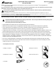
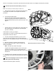
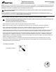
2. To test the Drive Belt tension:
• Push the Drive Belt downward at the midpoint (M)
between the pulleys and measure the distance. The
Drive Belt should have only 0.25” (0.64 cm) of give. See
Figure 1.
Or:
• Hold the edges of the Drive Belt at the midpoint (M) and
twistit(seeFigure2).Itshouldturnonly90degrees
(1/4 turn, to vertical).
If the tension is correct, go to Step 6.
If the tension is too loose or too tight, adjust the position of
the Flywheel. Continue to Step 3.
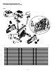
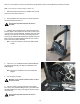
3. ToloosentheFlywheelhardware(A),usea15mm
open end wrench to hold the nut on one side steady and
loosen the nut on the opposite side with a 15 mm socket and
wrench.
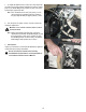
4. Move the Flywheel in the Main Frame bracket as
necessary to adjust the tension. Hold it in position and
tighten the hardware.
Note: This step may require two people.
To tighten the Flywheel hardware, use a 15 mm open
end wrench to hold the nut on one side steady and
tighten the nut on the opposite side with a 15 mm socket
and wrench.
5. Carefully turn the crank arms and check the movement
ofthedrivebelt.TheCrankArmsandFlywheelshouldmove
as one.
!
Be sure to keep ngers clear of all pinch hazards
when you turn the Drive Pulley.
Adjustthebelttensionagainifnecessary.
!
Disconnect all power to the machine before you service it.
NOTICE: It is necessary to remove the Shrouds for this procedure. Refer to the “Replace the Shrouds” procedure.
Figure 1
Figure 2
M
A
0.25”
0.64 cm
}
M
(Main Frame bracket not shown for clarity)