
User Manual


46
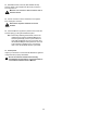
Note: Your machine may not match the image. For reference only.
1. Carefully remove the Shrouds. Refer to the “Replace the
Shrouds” procedure.
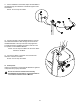
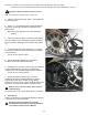
2. Insert2.5”x10”cardboardbetweentheBrakeMagnet
(A)andtheFlywheel(B),andtapethecardboardtothe
Brake Magnet.
Note: Be sure the cardboard covers all of the Brake
Magnet.
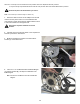
3. Using the needlenose pliers, unhook the Tension Spring
(G) from the Main Frame. Pull back and release the Magnet
Arm(H)enoughtodisengageitfromtheMotorPulleyShaft
(J).
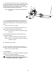
4. Loosenandremovethehexheadbolt(C),nut(D)and
washer(E)thatattachtheBrakeAssembly(A)totheMain
Frame bracket (F).
NOTICE: Do not crimp the cables
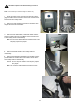
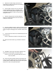
5. RemovetheBrakeAssembly(A).Removethe
cardboard.DiscardtheoldBrakeAssembly.
6. Installation is the reverse procedure. Tape the cardboard
to the new Brake Magnet. Be sure the cardboard will
completely cover the new Brake Magnet before installation.
NOTICE: Do not crimp the cables.
7. Before fully attaching the Shrouds, remove the
cardboardfrombetweentheBrakeMagnet(A)andthe
Flywheel (B). Power up the machine to verify that the
MagnetArmcanmovefreely,andthattheBrakeMagnetand
Flywheeldonottouchatthemaximumresistancelevel.
!
Machine is on. Current is active. There is risk of
electrical shock.
If necessary, refer to the “Set the Brake Tension” procedure.
8. Final Inspection
Inspect your machine to ensure that all hardware is tight and
components are properly assembled.
!
Do not use until the machine has been fully
assembled and inspected for correct performance
in accordance with the Owner’s Manual.
Disconnect all power to the machine before you service it.
NOTICE: It is necessary to remove the Shrouds for this procedure. Refer to the “Replace the Shrouds” procedure.
It may be necessary to adjust the Brake tension at the end of this procedure. Refer to the “Set the Brake Tension” procedure.
A
C
B
H
J
G
F
E
D
A