
User Manual

49
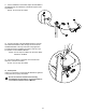
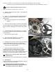
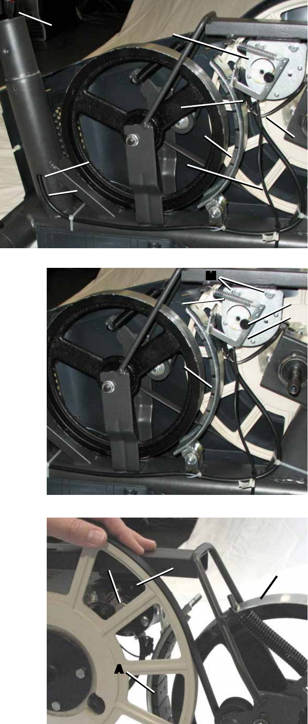
5. Observe the cable routing. Disconnect the
Speed Sensor Cable (D) and Power Inlet Cable (E)
from the wiring harness (F).
6. Tie the length of string to the end of the lower
Console Cable (G) at the top of the Mast mount.
Pull the cable and string down through the hole (H)
atthebaseoftheMastsothatthestringextends
through the mast.
7. Untie the string from the Console Cable (G).
RemovetheziptiesthatattachthelowerConsole
Cable (G) to the Frame.
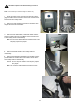
8. Using the needlenose pliers, unhook the Tension Spring
(J) from the Main Frame. Pull back and release the Magnet
Arm(K)enoughtodisengageitfromtheMotorPulleyShaft
(L).
9. Loosenandremovethetwohexheadbolts(M)fromthe
Servo Motor (C).
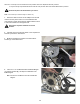
NOTICE: Hold the Servo Motor so that it does not fall.
10. Remove the Servo Motor (C). Discard the old Servo
Motor.
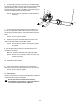
11. Installationisthereverseprocedure.Adjustthenew
Servo Motor to same position recorded in Step 3.
NOTICE: Do not touch the Potentiometer (N). Do not
crimp any cables.
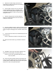
12. Tie the end of the string at the base of the Mast to the
end of the Console Cable (G) on the new Servo Motor (C).
Carefully pull the cable through the hole (H) to the top of the
Mast mount. Untie the string and discard it.
G
F
E
D
A
C
G
H
K
L
J
M
A
A
C
N
B