
Installation Manual
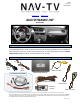

BHM
11/21/17
NTV-DOC242
Agreement: End user agrees to use this product in compliance with all State and Federal laws. NAV-TV Corp. would not be held liable for
misuse of its product. If you do not agree, please discontinue use immediately and return product to place of purchase. This product is
intended for off-road use and passenger entertainment only.
4 | P a g e
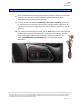
CAN Gateway
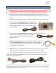
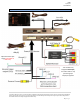
7. Grab the provided Power/CAN Harness from the AUDI-DYN-
INT kit. Use the chart below to locate and solder (splice,
don’t cut) the following wires to the car (you may have to
extend a pair of CAN wires for some vehicles):
AUDI A4, A5 CAN & Power Wires Location
Vehicle
Interface wires
Connect to AUDI Wire:
Wire Location
ALL
GROUND (Black)
Brown (Ground -)
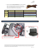
CAN Gateway
POWER (Red)
Black/White (ACC +)
CAN Gateway
A4/
A5/Q5
CAN 1 HI (Blue)
CAN HI (Orange/Blue)
CAN Gateway (Right side of radio.
Must remove glove box for access.)
CAN 1 LO (White)
CAN LO (Orange/Brown)
CAN 2 HI (Green)
CAN HI (Orange/Green)
CAN Gateway (Right side of radio.
Must remove glove box for access.)
CAN 2 LO (Pink)
CAN LO (Orange/Brown)
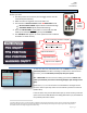
Without
MOST
Fiber
CAN Gateway location ALL INT MMI:
Right side of radio (drop glove box)