
Installation Manual
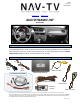

BHM
11/21/17
NTV-DOC242
Agreement: End user agrees to use this product in compliance with all State and Federal laws. NAV-TV Corp. would not be held liable for
misuse of its product. If you do not agree, please discontinue use immediately and return product to place of purchase. This product is
intended for off-road use and passenger entertainment only.
8 | P a g e
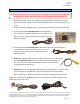
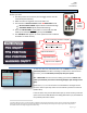
Adding HD-LINK Adapter (HDMI Input)
Follow the instructions below when adding the HDMI adapter
(HD-LINK) to enable HDMI input to the OEM screen:
1. Put dip switch #1 in the DOWN position.
2. Activate the ‘NAV INPUT’ by pressing the provided push
button (must be connected to module).
3. Once ‘NAV INPUT’ shows on the screen, on the remote
press the OK BUTTON 4 times, then press POWER.
4. Navigate to the ‘NAVI’ section.
a. Select ‘HDMI-SEL’
b. Choose ‘HD95E’
c. Press MODE on the remote to return and exit the OSD menu
(or let it time out).
5. Replace dip switch #1 to the UP position.
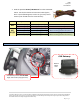
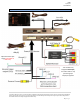
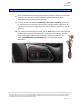
6. Connect the black wire to ground (-) and the red wire to ACC power
(+) from the main power connector on the HD-LINK adapter. The
RCA’s on this plug provide audio from the HDMI source.
Green Trigger wire setup
This module includes a green input wire for analog triggering of either the Reverse camera input or the
‘AVIN’ input (yellow RCAs), selectable through the AV menu. This allows for adding multiple cameras
through the use of an SVS-6 switcher, etc. Follow the steps below adjust this feature. NOTE: by default,
the green wire will trigger the Reverse camera input RCA.
1. Put dip switch #1 in the DOWN position. When this section is complete, return switch #1 UP.
2. Activate the ‘NAV INPUT’ by pressing the push button provided with the kit (connect to module).
3. Once ‘NAV INPUT’ shows on the screen, on the remote press the OK BUTTON 4 times, then
press POWER.
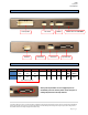
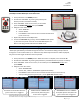
4. Navigate to the ‘SET’ section.
o Select ‘REVERSE WIRE’
o Choose ‘AV1’, ‘REAR’ or ‘REAR MODE’ (explanations below)
o Press MODE on the remote to return and exit the OSD menu (or let it time out).
o Test by sending temporary power (12v +) to the green wire labeled reverse.
AV1 shows the ‘AVIN’ RCA when the
green reverse wire is triggered.
REAR MODE shows the ‘CAMERA’
RCA (with dynamic lines) when the
green reverse wire is triggered.
REAR shows the ‘CAMERA’ RCA
(with no lines) when the green
reverse wire is triggered.