
User's Manual

| 19
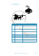
Wiring | Halo pulse compression radar installation manual
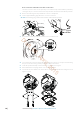
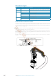
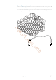
Scanner connector
Cable connector
Diameter = 23 mm
Pin-
out
Wire color
1 Black Pedestal power DC (-)
2 Red Pedestal power DC (+)
3 Yellow
4 Drain Tinned wire
5 N/A N/A
6 Blue RJ45 Pin 4
7 White / Blue RJ45 Pin 5
8 White / Brown RJ45 Pin 7
9 Brown RJ45 Pin 8
10 White / Green RJ45 Pin 3
11 N/A N/A
12 White / Orange RJ45 Pin 1
13 Green RJ45 Pin 6
14 Orange RJ45 Pin 2
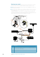
RJ45 Connector pinout
P1P8
Pin Color
1 White/Orange
2 Orange
3 White/Green
4 Blue
5 White/Blue
6 Green
7 White/Brown
8Brown
Required to complete
RJ45 Connector RJ45 Crimping tool
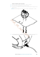
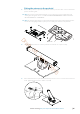
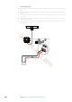
Connect the power cable
Power for the radar is connected to the RI-12 Interface module. The radar requires either a 12 or
24 V DC supply capable of delivering 20 Amps continuous.
The RI-12 is protected against reverse polarity, over voltage and under voltage. The RI-12 must
be connected to a dedicated fuse/circuit breaker. The fuse/circuit breaker should be labeled
accordingly.
Voltage Cable length
2 m (6.6 ft) 5 m (16.4 ft) 10 m (32 ft) 20 m (66 ft)
12 V DC 2.1 mm (12-AWG) 3.3 mm (8-AWG) 4.1 mm (6-AWG) N/A
24 V DC 1.3 mm (14-AWG) 2.1 mm (12-AWG) 3.3 mm (8-AWG) 4.1 mm (6-AWG)
Note: The RI-12 has an optional remote power control mode that can enable a compatible
multifunction display or ignition switch to control the power state of the radar (see “Remote
power control” on page 22)
Draft_08_April_2015