RS100/RS100-B V100/V100-B USER MANUAL ENGLISH RS100/RS100-B V100/V100-B www.simrad-yachting.com | www.bandg.
Preface Disclaimer As Navico is continuously improving this product, we retain the right to make changes to the product at any time which may not be reflected in this version of the manual. Please contact your nearest distributor if you require any further assistance. It is the owner’s sole responsibility to install and use the equipment in a manner that is legal and will not cause accidents, personal injury or property damage.
B&G® V100 Blackbox VHF Radio System • NRS-1 Marine VHF Radio Processor • H100 Wired Handset B&G® • SP100 Wired Speaker B&G® V100-B Blackbox VHF + AIS Radio System • NRS-2 Marine VHF Radio & AIS Class-B Processor • H100 Wired Handset B&G® • SP100 Wired Speaker Optional components Wireless Handset SIMRAD (HS40) Wireless Handset B&G (H60) Wireless Antenna Extension cable, 6 meters (CW100-6) Handset Cable, 20 meters (CH100-20) Handset Extension cable, 10 meters Licensing information • • • • • The user is a
EU RF exposure compliance notice for fixed mount VHF To be protected against all verified adverse effects, the separation distance of at least 2.1 m must be maintained between the antenna of the radio having max. 6 dBi antenna and all persons.
protection against harmful interference in a residential installation. This equipment generates, uses and can radiate radio frequency energy, and, if not installed and used in accordance with the instructions, may cause harmful interference to radio communications. However, there is no guarantee that interference will not occur in a particular installation.
prohibited for use with this device. Le présent émetteur radio a été approuvé par Innovation, Sciences et Développement Économique Canada pour fonctionner avec les types d’antenne énumérés ci-dessous et ayant un gain admissible maximal et l’impédance requise pour chaque type d’antenne. Les types d’antenne non inclus dans cette liste, ou dont le gain est supérieur au gain maximal indiqué, sont strictement interdits pour l’exploitation de l’émetteur.
MMSI and ATIS ID The user MMSI (Marine Mobile Service Identity) is a unique nine digit number. It is used on marine transceivers that are capable of using DSC (Digital Selective Calling). • An MMSI remains with a vessel, even if the vessel is sold on. • Your vessel MMSI must be assigned to you by an approved authority. It is illegal to use a self-assigned (made up) MMSI number. • A Group Call ID begins with ‘0’ followed by 8 numeric digits (0xxxxxxxx).
Contents 11 General information 11 13 14 18 How to display and navigate menus LCD functions Keypad functions Wired Handset Numeric Keys 18 Radio menus 18 19 20 20 21 22 25 27 28 30 31 32 34 Menu tree Scan Watch Voice recorder Display Radio setup DSC/ATIS setup AIS setup Alarms Handsets Using the wireless handset Diagnostics Reset 35 DSC call menu 35 37 38 38 DSC Calls Track buddy Contacts Call logs 39 AIS menu (NRS-2 only) 39 39 39 39 About AIS AIS receiver function AIS transmitter function AIS infor
47 Installation 47 48 49 50 51 52 54 55 59 60 What’s in the box Mounting guidelines Mounting the Blackbox Mounting the CR100 Fixed handset cradle Mounting the BC-12 wireless handset cradle Mounting the Speaker Wiring guidelines Blackbox connector details Wiring diagram First time startup configuration 63 VHF Radio Help and Troubleshooting Guide 63 63 63 63 63 63 63 64 Software updates Factory Reset System Diagnostics screens My VHF shortcut Power LED AIS LED (NRS-2 only) AIS Pop-up warning messages Troub
79 Dimensional drawings 80 80 81 81 82 NRS-1 and NRS-2 Blackbox HS100 and H100 Fixed Handset SP100 Speaker Handset Cradle (CR100) / Charger (BC-12) HS40 / H60 Wireless Handset 82 Appendix 83 Country Settings table 84 NMEA 2000 compliant PGN list Contents | User Guide Style Template | 11
1 General information The RS100 / V100 system provides the following features: • Up to 4 wired alphanumeric handset stations • Up to 4 wireless handsets (HS40/H60) • 4 configurable 4 W wired speaker outputs • Built-in GPS processor for connection with an external GPS antenna • Audio Playback function • Intercom, Fog Horn, and Hailer functions • Man Over Board (MOB) function • Navigation (NAV) function • TRI key to select DUAL/TRI scan • Dedicated Wx (Weather) key • Favorite channels list to build your list
D Current menu item selected is highlighted. E Arrow indicates additional sub-menu items for the menu option. ¼ Note: Press the X/POWER key to step backwards to the previous menu page, or exit the menus completely. Press the OK/HL key to make selections in the menu. Entry of alphanumeric data Press the and keys to scroll through the alphanumeric characters, or use the keypad on the wired handset to enter text (i.e, press the 5 key 2 times to enter the letter K).
Missed DSC call Low Battery (vessel) warning (activates at 10.5 V) Battery level (wireless handset) Track your Buddy feature is active TRI watch or DUAL scan is active GPS simulator is active LCD functions A B C D E F G H I J K L M N O P Q R S T U V W X Y Z AA AB 14 | Radio is Transmitting (TX) mode.
Keypad functions A Distress A Distress call is broadcast to all DSC equipped radios, so will create an alarm on every DSC radio within range. If position information is available it will be included in the transmission. Short press to commence a distress call. Nature of the distress can be selected from the list. Long press to initiate an immediate ‘undesignated’ distress call. B 16 / 9 Short press to change to the priority channel CH16. Press again to return to original channel.
¼ Note: Also used for menu scrolling, editing, and backlight level adjustment. F Channel DOWN Short press decreases one channel. ¼ Note: You can also directly select a channel by typing the channel number on the keypad. Long pressing the key will, after a short delay, step rapidly through the channels. ¼ Note: Also used for menu scrolling, editing, and backlight level adjustment. G OK / HL Short press to make selections in menus.
P Q R S T • Normal radio mode: Short press to start DUAL WATCH or TRI WATCH (if ‘watch’ channel set). Refer to “Watch” on page 21 for more details. Long press to set the current channel as the watch channel. • AIS mode (NRS-2 only): Short press to increase (zoom out) the scale of the AIS plotter in one range at a time. The scales available are: 1, 2, 4, 8, 16, 32 nm. MOB (SCAN+TRI) Long press both keys simultaneously to mark the current location with a Man-Over-Board (MOB) waypoint.
Wired Handset Numeric Keys Depending on the mode the radio is in, the numeric keys on wired handsets provide additional functionality. • NORMAL mode - System is in standby: Short press enters the numeric digit (i.e. channel number). Long Press opens a pre-determined function or menu. • DATA INPUT mode - Entering data in a menu: Short press enters the numeric digit. Subsequent presses enters a letter. The displayed letter is accepted after a short pause, or on pressing a different key.
2 Radio menus Menu tree Long press the DSC/MENU key to open the main Menu page. The following shows the available menu and submenu options: ¼ Note: Main (first) level and 2nd level only.
NRS-2 only AIS FUNCTION AIS setup SILENT MODE AIS DISPLAY CPA TCPA CONFIG VESSEL GPS ALERT WX ALERT (ON/OFF) (MMSI/NAME) (>) (>) (>) (>) (>) DSC ALARM CPA ALARM WIRELESS HANDSET CONFIGURE HANDSET GPS STATUS SYSTEM DIAGNOSTICS NMEA2000 STATUS AIS DIAGNOSTICS HANDSET STATUS SELECT REGION/COUNTRY SYSTEM RESET (>) (>) (>) (>) (>) (>) (>) (>) (>) SELECT REGION (YES/CANCEL) Alarms Handsets Diagnostics Reset NRS-2 only NRS-2 only NRS-2 only NRS-2 only NRS-2 only US/CAN country modes Key: ) - a checkbox
My channels + 16 Scans all channels selected in EDIT MY CHANNELS, while also checking the priority channel after every channel step. Edit my channels ¼ Note: This function is also available as a Shortcut. Allows creation of a custom list of channels - used in a MY CHANNELS scan. Watch This menu is for choosing a watch mode to enable, as well as selection of the watch channel.
Recorder • • ON - Record transmitted and received VHF audio (loop recording last 60 seconds). OFF - Disables voice recorder. Display This menu allows the user to partially customize the screen information displayed, and adjust the screen for best visibility to suit the user and operating conditions. Time display Select ON or OFF to display TIME. LOC (Local Time) is displayed below the time if a UTC (Coordinated Universal Time) offset has been entered; otherwise UTC is shown.
Network max level Select a maximum level. This is to ensure the backlight is never too bright if the network level is set too high. Select between 5 to 10. ¼ Note: Backlight Offset settings relate to the individual handset, not to the system. ¼ Note: If the backlight level is changed on the handset the radio will send the backlight level to the network excluding the offset. Contrast ¼ Note: This function is also available as a Shortcut.
Units Select SPEED to choose KNOTS, MPH, or KPH. Select COURSE to choose MAGNETIC or TRUE. A true north heading is corrected for magnetic variation. A magnetic north heading source must also output magnetic variation data if the heading is to be displayed as a true north value. Handset speaker ¼ Note: This function is also available as a Shortcut. Select to switch the handset’s internal speaker ON or OFF. Wired speaker External speaker ¼ Note: This function is also available as a Shortcut.
GPS source ¼ Note: This function is also available as a Shortcut. Depending on your radio blackbox model, you can select between a Networked GPS source (NRS-1) or Internal GPS source (NRS-1 and NRS-2). ¼ Note: A valid GPS source is required for DSC and AIS functions to operate. ¼ Note: Due to AIS regulations, it is not possible to use a Networked GPS source with an AIS transmitter, so is not available for the NRS-2 model.
Time Time offset ¼ Note: This function is also available as a Shortcut. Select TIME OFFSET to enter the difference between UTC and local time in 15 minute increments with a maximum offset of ±13 hours. ¼ Note: Does not automatically adjust for Daylight Savings Time. Time format ¼ Note: This function is also available as a Shortcut. Select to toggle between 12 and 24 hour format. Vessel call sign Select to enter vessel call sign. Used by the MOB and AIS functions.
ATIS ID (EU country mode only) Enter an ATIS number to access the radio’s ATIS functionality. This unique identifier must be supplied a local radio spectrum authority. DO NOT enter a random ‘made up’ number. ¼ Note: Contact a Simrad or B&G dealer if you need to change your ATIS ID after initial input.
DSC timeout An inactivity timeout can be set to return the radio to normal operational mode after a period of inactivity while the radio is engaged in a Distress or non-Distress DSC call: Distress Select between NONE, 5 MINS, 10 MINS and 15 MINS. (default is NO TIMEOUT). Non distress Select between NONE, 5 MINS, 10 MINS and 15 MINS. (default is 15 MINS). AIS setup ¼ Note: This section relates to systems using the NRS-2 blackbox only.
Additional Vessel data will be transmitted once these details are completed. Ship name Call sign MMSI Vessel type A B C D Enter the ship’s name; maximum 20 alpha-numeric characters. Enter your VHF radio call sign – this must be supplied from your local radio spectrum authority. Will automatically show if it was entered during the initial startup of the radio. Your DSC MMSI number. Will automatically show if it was entered during the initial startup at first turn on of the radio, or during DSC setup.
GPS alert The GPS alert is a warning to the user that the selected GPS source is not outputting valid position data. It comprises of an audible alarm and visual alarm (screen flash and warning text). GPS alert function If set to OFF, there will be no GPS alerts including audible alarm, screen flash, and warning text.
In this case, the T/CPA calculation deems the vessel UNSAFE and the TCPA Alert is raised. If set to OFF, there will be no T/CPA alarms regardless of the settings. It comprises of an audible alarm and visual alarm (screen flash and warning text). CPA alert function If set to OFF, the radio will not respond to T/CPA alerts including audible alarm, screen message, and screen flash.
Wireless handset (WHS) Pair a wireless handset The pairing process only needs to be performed once per WHS: 1 Ensure the WHS that you want to pair to the radio is charged and turned OFF. ¼ Note: Ensure all other WHS’s remains OFF during this procedure. 2 Access the radio’s Main menu from a fixed handset, and select HANDSETS > WIRELESS HANDSET. 3 Select PAIR A HANDSET. Select YES. 4 Turn ON the wireless handset that you want to pair to the radio. The WHS display will show SEARCHING...
Once the wireless handset has been paired to the radio, the screen and key functionality are mimicked on each device. Most functions that are provided on the radio can be accessed by the wireless handset with the following exceptions: • SETUP - Some setup functions are not available on the wireless handset. • HAILER - It is not possible to enter HAILER mode from the wireless handset. When the wireless handset is not in use, it should be placed back into the charger cradle.
• HANDSET STATUS: Fixed Handset installed and turned ON Fixed Handset installed and turned OFF This handset Wireless Handset installed and turned ON NMEA2000 status ¼ Note: This function is also available as a Shortcut. Select to view the NMEA 2000 network diagnostics: • • • • • • BUS STATE: Displays if the radio is active on the vessels NMEA 2000 Network TX ERRORS: Displays any current transmit errors on the vessels NMEA 2000 Network. Not a cumulative counter.
Reset Region and Country Use this setting to change the Region and Country settings this radio is operating in. ¼ Note: Refer to “Country Settings table” on page 94 for a listing of the Countries supported. If your Country is not listed, select INTERNATIONAL 1 First select the Region: EUROPE, USA/CAN or INTERNATIONAL 2 Then select the Country within the selected region. If your country is not listed, then select INTERNATIONAL > INTERNATIONAL 3 Once the Country is selected, the radio is restarted.
3 DSC call menu Digital Selective Calling (DSC) is a semi-automated method of establishing VHF, MF, and HF radio calls. One big advantage that DSC enabled radios offer is that they can receive calls from another DSC radio without being on the same channel as the calling radio. Short press the DSC / MENU key for the following options: • DSC CALLS • TRACK BUDDY • CONTACTS • CALL LOGS DSC Calls The calling radio may provide details on what channel to switch to so that voice communication can be established.
Send a distress call using the DISTRESS key 1 Lift the red protective cover exposing the Distress key. 2 Short press the Distress key. Use the and keys to select the nature of distress call from the menu. 3 Long press the Distress key. A 3-second countdown will commence before the Distress call is sent. After the Distress Call is sent, the radio waits for an acknowledgment. The Distress Call is automatically re-sent every 3.5 to 4.5 minutes until a distress acknowledgement (DISTRESS ACK) is received.
POS REQUEST Used to request a position of another vessel. The call can be initiated by selecting: • MANUAL: enter a new vessel’s MMSI • RECENT: select a vessel in the RECENT list • CONTACTS: an existing vessel already saved in your CONTACTS list POS REPORT Used to send your vessels position to another vessel.
INTERVAL The frequency that ‘buddies’ are polled with position requests can be selected between: 5, 15, 30 and 60 minutes. Contacts Used for the administration and calling of CONTACTS and GROUPS. VIEW/ADD CONTACT Use this to create, edit, or delete up to 50 vessel CONTACTS with names and MMSI’s. Contacts are stored by name, in alphabetical order. Select ADD NEW to create a new contact.
4 AIS menu (NRS-2 only) ⚠ Warning: Valid GPS data must be entered into this radio before the AIS functions can be used. The plotter PPI function will not display targets accurately with incorrect GPS data. ⚠ Warning: Take note that not all vessels will have an AIS transceiver installed or turned on, so will NOT be taken into consideration for Collision Avoidance. ⚠ Warning: Not all vessels transmit AIS information and therefore will be displayed or listed in the following AIS screens.
2 AIS target details will be displayed on the left of the screen. Either the vessels name or MMSI will be displayed (if the information is available) depending on the setting you selected in Section “6-2 AIS data display format (AIS DISPLAY)”. Also the target’s bearing and distance to you are displayed. ¼ Note: It could take some time before AIS targets are displayed.
5 Fog Horn, Intercom, and Hailer ¼ Note: An appropriate Hailer speaker must be connected to the Hailer wiring before the HAILER or FOG HORN functions can be used. Using the FOG Horn The FOG horn will sound certain international standard fog horn tones through the Hailer speaker depending on the mode selected. 1 Long press the AIS/IC key to enter IC/HAILER mode: 2 Select FOG HORN and press the OK key.
Using the HAILER The Hailer function allows you to make a high volume announcement using the handset through the Hailer speaker to people or vessels. The Hailer function also features a LISTEN mode - this mode uses the Hailer speaker as a microphone to listen for a response on the main radio. LISTEN mode is not available on the optional wireless handset. 1 Long press the AIS/IC key to enter IC/HAILER mode. 2 Select HAILER and press the OK key. 3 Press the PTT key to talk through the hailer.
6 My channels The MY CHANNELS page is accessed by long pressing the numeric 9 key. This page provides a shortcut to frequently accessed channels. The first time this page is opened, the entire channel list is shown so that the desired shortcut channels can be selected. Subsequent opening of this page will show a list of only the selected channels. Choosing one of the channel options immediately exits the page and sets the radio to that channel.
7 Shortcuts The Shortcuts page is accessed by long pressing the VOL/SQL selector key. This page is provided as a shortcut to frequently accessed functions. The shortcut options available on this page are subject to selections made in ADD/EDIT SHORTCUTS. Add/Edit Shortcuts Long press the VOL/SQ selector key.
8 MOB and NAV functions Man Over Board (MOB) An MOB is generated by press and hold SCAN and TRI keys together. The screen will change to MOB navigation mode to help navigate back to the MOB location: • • DST shows the current distance to MOB waypoint. STEER shows the current bearing to MOB waypoint direction indicators showing: • for turn to port, • for straight ahead, and • for turn to starboard. ¼ Note: An MOB waypoint is sent to a connected MFD via NMEA 2000.
Navigation Function (NAV) Long press 6 to enter the NAV (Navigation) mode. The screen will change to navigation mode displaying the vessel’s current SOG and COG Press the X / POWER key to exit NAV mode and return to normal radio operation mode.
9 Installation What’s in the box The following items should be supplied in the box. Check before starting the installation and contact your dealer if an item is missing. ¼ Note: A VHF antenna is not provided. Consult your Simrad or B&G dealer for advice on selecting the correct antenna for your installation. ¼ Note: Systems utilizing the NRS-2 Blackbox requires an additional VHF/AIS antenna which is not provided.
6.2 6.3 6.4 6.5 7 S/S Pan-head machine screw (M3 x 20) S/S flat washer (M3) S/S split washer (M3) S/S hex nut (M3) Warranty card 2 2 2 2 1 Wired Speaker with the following items: No.
Mounting the Blackbox ¼ Notes: Allow easy access to the Blackbox for connection to the 12 V DC power supply, the antenna(s), and additional wiring. • The Blackbox can be positioned vertically on a bulkhead or horizontally. Avoid positions that might get wet or hot, such as in the engine compartment or close to the bilge. • The Blackbox is not water-proof. • If mounting the Blackbox vertically, ensure the wiring glands are facing downwards in order to prevent the ingress of water.
Mounting the CR100 Fixed handset cradle ¼ Notes: • The CR100 Fixed handset cradle is a passive unit and does not require a power supply. • The Fixed handset is provided with a 5m (16.4’) handset extension cable. Ensure the chosen location is within the length of the installed cable to the Blackbox. • Longer lengths of handset extension cable is available from your dealer. • The handset LCD screen has an optimum horizontal and vertical viewing angles within approx. +/-20 deg.
Mounting the BC-12 wireless handset cradle ¼ Notes: • The BC-12 Wireless Handset Cradle requires a +12V DC supply for charging. Ensure the selected location allows for the power wire at the rear of the unit. • The handset LCD screen has an optimum horizontal and vertical viewing angles within approx. +/-20 deg. Ensure the chosen location provides a suitable view of the display. Ideally, you should be directly in front of the display or no more than +/-20 degrees from the front of the display.
Mounting the Speaker ¼ Note: The wired speaker is provided with a 2m (6.5’) fixed cable. The cable maybe extended if necessary using a minimum 14 AWG 2-pair cable. Flush mounting 1 Cut a 98 mm (3.86”) diameter hole in the mounting surface, allowing space for the speaker’s overall dimensions. 2 Remove the plastic bezels that cover the screw holes. Temporarily fit the speaker and mark the four screw holes. 3 Drill holes of appropriate size for fasteners to be used.
Surface mounting 1 Remove the plastic bezels that cover the screw holes on speaker front. Mark the screw holes using the speaker as the template. 2 Drill holes of appropriate size for the fasteners to be used. • Drill a hole in the mounting surface for the speaker wire, ensuring hole is near one of the corner screw holes, to prevent cable pinching under speaker. 3 Feed speaker wire through surface mount box and through mounting surface hole. • Apply sealant around the cable hole and the screw holes.
Mounting the GPS-500 antenna ¼ Note: The GPS-500 antenna is only optional for NRS-1 but mandatory for NRS-2. • It is not recommended that the GPS antenna is mounted up a mast where the motion of the vessel will cause the antenna to swing and potentially reduce the accuracy of the GPS position. • Do not mount the GPS antenna within 1 m of a transmitting device. Mount the GPS-500 externally to either a (A) pole or (B) hard surface then run the cable to the Blackbox.
Do’s: • Make drip and service loops. • Use cable-tie on all cables to keep them secure. • Solder/crimp and insulate all wiring connections if extending or shortening the cables. Extending cables should be done with suitable crimp connectors or solder and heat shrink. Keep joins as high as possible to minimize possibility of water immersion. • Leave room adjacent to connectors to ease plugging and unplugging of cables. • Connect the radio to a 12 V DC, negative ground power supply.
Cable Grommets There are two cable sealing rubber grommets at the front of the Blackbox. Wires must pass through the allocated slot in the grommet (L1-7 and R1-7) as indicated to create an IPx5 seal. Slots have a thin rubber membrane to ensure unused slots remain sealed. Press the wire through the allocated slot to break the seal prior to adding the connector. 1 2 3 L 4 5 6 7 6 7 3 2 1 5 4 R To access the rubber grommets, remove the grommet retainer bracket.
B FUSE 10 A + - A GND 12V DC S1+ MIC+ MIC+ RX_A S1- MIC- MIC- RX_B S2+ PWR PWR TX_A S2- PTT PTT TX_B S3+ TR-B TR-B HRN- S3- TR-A TR-A HRN+ S4+ GND GND SSW- S4- C PC VCC + - H HAILER SSW+ VCC SKP1-4 HS1 HS2 HS3 HS4 AUX D E F F F G GND (A) Optional ground connection. May help with induced noise issues. Ring terminal size M3, #5. FUSE (B) 10 A mini-blade type fuse.
AUX (G) Auxiliary connections for NMEA 0183, Horn key and AIS Silent Switch: RX_A RX_B TX_A TX_B HRNHRN+ SSWSSW+ RA RB TA TB HH+ SS+ NMEA 0183 TX_A of chart plotter, or GPS data NMEA 0183 TX_B of chart plotter, or GPS data NMEA 0183 RX_A of chart plotter NMEA 0183 RX_B of chart plotter HORN. Connect a Normally Open, momentary switch AIS Silent Switch (NRS-2 only).
Wiring diagram A E D C B T T _ + F G G K L H I M N + _ A B C D E F G H I J K L M N 60 | J AIS Antenna (NRS-2 only) GPS-500 (NRS-1 optional; NRS-2 mandatory) NMEA 2000 GPS Source (Optional on NRS-1 only) Navico MFD VHF Antenna Wireless Dipole Antenna (Optional 6 meter extension cable available) Fixed Handsets (HS1 mandatory, HS2, HS3, HS4 optional) Wired Speakers (Optional - 4 max) Breaker/Power Switch 12V DC Power Supply NRS-1 / NRS-2 Blackbox HAILER/HORN Speaker Silent Switch (NRS-2 only)
First time startup configuration ⚠Warning: Never operate the radio without the antenna connected. This may damage the transmitter. The first time the radio is powered up, the user is prompted to make a series of setting selections in order to allow the radio to perform to its full potential. Some steps must be completed; some are optional and can be completed later.
6 Set the time offset for your region. Time Offset in 24 hour format: 7 Select 12 HOUR or 24 HOUR format: 8 Select CONFIGURE AIS to configure CLASS-B AIS (NRS-2 only).
10 VHF Radio Help and Troubleshooting Guide This guide aims to help resolve an issue you may encounter with the system during installation or operation. In some cases, a restart of the system may remedy the situation; however, other steps may need to be followed such as performing a factory reset. Additionally, refer to the built-in system diagnostics screens to assist in resolving issues. Software updates The System software can be updated via the NMEA 2000 network using a connected Simrad/B&G MFD.
Error type Reason Details 2 Error message AIS VSWR ERROR! Pop-up message AIS antenna VSWR detection (open circuit or short circuit) Detect at each AIS transmission. Either the antenna is missing (open circuit), or damaged (short circuit). Can also be due to corrosion of wiring or connections. Can continue operating, however Tx and Rx will be affected. Recommend replacing antenna. 3 AIS CHANNEL ERROR AIS Icon flashes ERR AIS channel background noise exceeds -77dbm Detect every 4 seconds.
9 10 11 No sound from wired speaker 12 13 No GPS fix 14 Incorrect wiring Confirm wiring is correct Volume is set too low Check volume is not at minimum and adjust as required Incorrect speaker assignment Check speaker assignments including offset value. You may need to set a minimum offset value so speaker volume does not go too low Incorrect GPS Source Setting Check GPS Source is correct – Internal or Networked Antenna covered External GPS antenna location unsuitable.
AIS Class-B (NRS-2 only) Issue Reason Details A VHF antenna must be connected to the AIS antenna port 1 No AIS Antenna 2 All details in the AIS setup screen must be AIS details not completed completed before the AIS system can commence transmitting. AIS won’t TX 3 No MMSI A valid MMSI must be added before the AIS system can commence transmitting 4 No GPS fix A GPS fix must be obtained 5 Silent Switch is ON The AIS system will receive but not transmit while Silent mode is active.
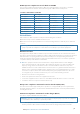
11 RS100/B, V100/B Specifications System features Local/Distant control: LL Position polling: Group call: Call logs: Channel naming: Handset naming: Dual watch / Tri watch: Favorite channel scan: All scan: User programmable MMSI: User programmable ATIS ID: MMSI and NAME directory: Software updates: Yes Yes Yes Yes - 20 individual and 10 distress Yes Yes Yes Yes Yes Yes Yes Yes - 50 vessel contacts and 20 group contacts Yes, via NMEA 2000 Technical Power supply: Current drain: Replacement fuse: Temperat
Waterproof: Weight: NRS-1, NRS-2: IPx5 HS100, H100, SP100: IPx7 HS40, H60: IPx7 NRS-1, NRS-2: 2.5 kg (5.5 lbs) HS100, H100: 1.46 kg (3.2 lbs) SP100: 0.45 kg (1.0 lbs) VHF Transceiver VHF Mode: Usable channels (country specific): Channel spacing: Frequency stability: Frequency control: DSC mode: ATIS mode: 16K0G3E (FM) / 16K0G2B (DSC) International, Europe, USA, Canada, Weather 25 KHz ± 5 ppm PLL Class D (Global) with dual receiver (individual CH70) TX Deviation at 1.3K: 2.6 ± 0.26 KHz TX Deviation at 2.
Built-in GPS Receiver Receiving frequency: Tracking code: Number of channels: Horizontal accuracy: Position fixing time: Position update interval: 1575.42 MHz C/A code 72 channels <10 m Warm start: 30s, Cold start: 90s 1 second typical Wireless specifications Wireless standard: Operating frequency: Rx Sensitivity (802.11 b - 11 Mbps): Tx Power (802.11 b - 11 Mbps): Functional range: 802.11 b/g/n20 2412~2472 MHz (for EU); 2412-2462 MHz (for US) -86 dBm (+/-2) 9.
12 Channel charts The following channel charts are provided for reference only and may not be correct for all regions. It is the operators’ responsibility to ensure correct channels and frequencies are used for local regulations. EU and International channel chart With reference to Appendix 18 (Rev.WRC-15) (See article 52). ¼ Note: For assistance in understanding the table, see Notes a) to zz) below.
77 18 78 m) m) 1078 2078 19 1019 mm) m) 2019 79 mm) m) 2079 mm) m) 1079 20 1020 2020 80 21 81 22 82 23 83 24 1024 2024 1084 25 1025 1085 26 1026 71 | mm) y), wa) y), wa) y), wa) y), wa) x), y), wa) x), y), wa) x), y), wa) w), ww), x), xx) w), ww), x), xx) w), ww), x), xx) 156.875 156.900 156.925 156.925 x 157.025 157.050 157.075 157.100 157.125 161.500 161.525 156.925 161.525 161.550 156.950 161.550 161.575 156.975 161.575 161.600 157.000 161.600 161.625 161.650 161.675 161.700 161.
86 w), ww), x) 1086 w), ww), x) 2086 w), ww), x) 27 z), zx) 1027 z), zz) ASM 1 z) (was 2027) 87 z), zz) 28 z), zx) 1028 z), zz) ASM2 z) (was 2028) 88 z), zz) AIS 1 f ), l), p) AIS 2 f ), l), p) 157.325 161.925 x x x x x x x 157.325 161.925 157.350 157.350 161.950 157.350 161.950 161.950 157.375 157.400 157.400 162.000 157.375 162.000 157.400 162.000 x 157.425 161.975 162.025 157.425 161.975 162.
j) Channel 70 is to be used exclusively for digital selective calling for distress, safety and calling. k) Channel 13 is designated for use on a worldwide basis as a navigation safety communication channel, primarily for intership navigation safety communications. It may also be used for the ship movement and port operations service subject to the national regulations of the administrations concerned.
mobile service using digitally modulated emissions and subject to coordination with affected administrations. (WRC-15) wa) In Regions 1 and 3: • Until 1 January 2017, the frequency bands 157.025-157.175 MHz and 161.625-161.775 MHz (corresponding to channels: 80, 21, 81, 22, 82, 23 and 83) may be used for digitally modulated emissions, subject to coordination with affected administrations.
USA channel chart Channel designator 6 Transmitting frequencies (MHz) From ship stations From coast stations 156.300 156.300 S/D/R Channel name S SAFETY 8 156.400 156.400 S COMMERCIAL 9 156.450 156.450 S CALLING 10 156.500 156.500 S COMMERCIAL 11 156.550 156.550 S VTS 12 156.600 156.600 S PORT OPS/VTS 13 156.650 156.650 S BRIDGE COM 14 156.700 156.700 S PORT OPS/VTS 15 -- 156.750 R ENVIROMENTAL 16 156.800 156.800 S DISTRESS 17 156.850 156.
1080 (was 80A) 157.025 157.025 S COMMERCIAL 1081 (was 81A) 157.075 157.075 S RESTRICTED 1082 (was 82A) 157.125 157.125 S RESTRICTED 1083 (was 83A) 157.175 157.175 S RESTRICTED USA weather channels Channel designator WX1 WX2 WX3 WX4 WX5 WX6 WX7 Transmitting frequencies (MHz) From ship stations From coast stations -162.550 -162.400 -162.475 -162.425 -162.450 -162.500 -162.
Non-Weather-Related Events State and Local Codes-Optional Avalanche Watch Avalanche Warning Child Abduction Emergency Civil Danger Warning Civil Emergency Message Earthquake Warning Evacuation Immediate Fire Warning Hazardous Materials Warning Law Enforcement Warning Local Area Emergency 911 Telephone Outage Emergency Nuclear Power Plant Warning Radiological Hazard Warning Shelter in Place Warning Volcano Warning NWR-SAME Code Status AVA AVW CAE CDW CEM EQW EVI FRW HMW LEW LAE TOE NUW RHW SPW VOW Operat
Canada channel chart Channel designator Frequencies S/D/R Channel Name: D TELEPHONE D TELEPHONE 160.750 D TELEPHONE 156.200 160.800 D CANADIAN CG 5 156.250 160.850 D TELEPHONE 6 156.300 156.300 S SAFETY 7 156.350 160.950 D TELEPHONE 8 156.400 156.400 S COMMERCIAL 1 MHz (ship) 156.050 MHz (coast) 160.650 2 156.100 160.700 3 156.150 4 Restrictions 9 156.450 156.450 S VTS 10 156.500 156.500 S VTS 11 156.550 156.550 S VTS 12 156.600 156.
156.975 161.575 D TELEPHONE 80 157.025 161.625 D TELEPHONE 81 157.075 161.675 D TELEPHONE 82 157.125 161.725 D CANADIAN CG 83 157.175 161.775 D CANADIAN CG 84 157.225 161.825 D TELEPHONE 85 157.275 161.875 D TELEPHONE 86 157.325 161.925 D TELEPHONE 87 157.375 157.375 S PORT OPS 88 157.425 157.425 S PORT OPS 1001 156.050 156.050 S COMMERCIAL 1005 156.250 156.250 S PORT OPS/VTS 1007 156.350 156.350 S COMMERCIAL 1018 156.900 156.
NRS-1 and NRS-2 Blackbox 234.80 mm (9.24”) 212.0 mm (8.35”) 200.08 mm (7.88”) 190.0 mm (7.48”) 82.0 mm (3.23”) 79.0 mm (3.11”) 63.87 mm (2.51”) 190.0 mm (7.48”) 116.0 mm (4.57”) HS100 and H100 Fixed Handset 29.50 mm (1.16”) 68.0 mm (2.68”) 160.94 mm (6.
SP100 Speaker 109.5 mm (4.31”) 98.0 mm (3.86”) 18.77 mm (0.74”) 91.62 mm (3.61”) 101.0 mm (3.98”) 27.0 mm (1.06”) 110.0 mm (4.33”) 35.0 mm (1.38”) Handset Cradle (CR100) / Charger (BC-12) 65.7 mm (2.59”) 80 | 171.6 mm (6.75”) 74.9 mm (2.95”) 58.0 mm (2.28”) 55.7 mm (2.19”) 32.9 mm (1.29”) Dimensional drawings | RS100 / RS100-B / V100 / V100-B User Manual 54.6 mm (2.
40.9 mm (1.61”) HS40 / H60 Wireless Handset 67.9 mm (2.68”) 32.0 mm (1.26”) 74.0 mm (2.91”) 31.0 mm (1.22”) 161.0 mm (6.34”) 49.2 mm (1.
14 Appendix Country Settings table Region INTERNATIONAL Country INTERNATIONAL AUSTRALIA NEW ZEALAND USA/CAN UNITED STATES CANADA EUROPE AUSTRIA BELGIUM BULGARIA CROATIA CYPRUS CZECH REPUBLIC DENMARK ESTONIA FINLAND FRANCE GERMANY GREECE HUNGARY IRELAND ICELAND ITALY LIECHTENSTEIN LITHUANIA LUXEMBOURG LATVIA MOLDOVIA MALTA NETHERLANDS NORWAY POLAND PORTUGAL ROMANIA SLOVAK REPUBLIC SPAIN SERBIA SWEDEN SWITZERLAND SLOVENIA TURKEY UNITED KINGDOM 82 | Appendix | RS100 / RS100-B / V100 / V100-B User Manua
NMEA 2000 compliant PGN list PGN Description 59392 ISO Acknowledgement 59904 ISO Request 60160 Transport Protocol, Data Transfer 60416 Transport Protocol 60928 ISO Address Claim 65240 Commanded Address 126208 NMEA — Group Function 126464 PGN List 126992 System Time 126993 Heartbeat 126996 Product Information 126998 Configuration Information 127233 MOB Data 127250 Vessel Heading 127258 Magnetic Variation 128267 Water Depth 129025 Position, Rapid Update 129026 COG & SOG, R
PGN Description 129810 AIS Class B CS Static Data Report, Part B 130074 Route and WP Service - WP List -WP Name & Position 130306 Wind Data 130840 Source Selection 130842 AIS and VHF Message Transport 130845 Parameter Handle 130850 Event Command 130851 Event Reply (□) AIS-B model only (NRS-2) (◊) Only if GPS source = INTERNAL 84 | Appendix | RS100 / RS100-B / V100 / V100-B User Manual RX ● □ ● ● TX ● ● □ ● ●
*988-12732-001* ®Reg. U.S. Pat. & Tm. Off, and ™ common law marks. Visit www.navico.comintellectual-property to review the global trademark rights and accreditations for Navico Holding AS and other entities. www.simrad-yachting.com | www.bandg.
A1 初始版本 杨克华 许贵 黎树发 2020-09-23 单面印刷 Notes(技术要求): 1.Dimension after binding(尺寸):A5大小(148.5X210mm). 2.Print colour(印刷颜色):单黑印刷 3.Material(材质):80g书纸. 4.Binding process(装订工艺):无. 5.Tolerance(公差):L(长)*W(宽):±1.5mm. 6.所用材料及相关加工工艺必须符合RoHS及REACH指令标准,所有材料及其它原料必须和上 述规格型号一致,且未经许可不得擅自更改. 7.来货外包装箱必须符合环保要求,并打上"RoHS"标记。禁止使用“富创优越”管理规定之 有害物质. 深圳市富创优越科技有限公司 Shenzhen Fastrain Technology Co.
www.lowrance.com www.simrad-yachting.com www.bandg.com LIMITED WARRANTY GARANZIA LIMITATA GARANTIE LIMITÉE GARANTÍA LIMITADA ITALIANO (IT) FRANÇAIS (FR) ESPAÑOL (ES) 有限保修 BEGRÄNSAD GARANTI BEGRENSET GARANTI RAJOITETTU TAKUU EINGESCHRÄNKTE GARANTIE CHINESE (ZH) SVENSKA (SV) NORSK (NO) FINNISH (FI) DEUTSCH (DE) This product is covered by Lowrance Service and Support, refer to www.lowrance.com for more information. This product is covered by Simrad Service and Support, refer to www.simrad-yachting.
CHINESE (ZH) SVENSKA (SV) NORSK (NO) FINNISH (FI) DEUTSCH (DE) Navico 保证,自购买之日起,本产品一旦妥善安装并 投入使用,在一定期限内材料和制作工艺不会有任 何问题,这个期限就是在 www.simrad-yachting.com, www.lowrance.com, www.bandg.com, www.GoFreeMarine.com 网站上规定的相关产品和/ 或配件的期限(称为“保修期”)。 就保修目的而言,“第一次购买日期”是指第一位零 售客户购买该产品的日期,或者是由 Navico 批准/认 证的造船厂将产品安装到新的船舶上后,第一位零 售客户提取船舶的日期。 按照 www.simrad-yachting.com, www.lowrance.com, www.bandg.com, www.GoFreeMarine.