Jupiter GPS receiver module Designer’s guide (11/12/T/Pico/Pico T series) Related products Jupiter 11 (low power) • Development kit TU10-D007-051 Jupiter 11 (standard 5 V) • Development kit TU10-D007-061 Jupiter 11 (dead-reckoning) • Development kit TU10-D007-101 Jupiter 12 (standard) • Development kit TU10-D007-351 Jupiter 12 (dead-reckoning) • DR Development kit TU10-D007-352 Jupiter Pico (standard) • Development kit TU10-D007-361 Jupiter Pico (timing) • Development kit TU10-D007-363 Related docum
Contents Features .................................................................................................................................5 1.0 Introduction .................................................................................................. 6 1.1 Product overview ............................................................................................................6 1.1.1 Description ...............................................................................................
.5.2.13 Message 1303 (restart command). .............................................................................. 41 3.5.2.14 Message 1310 (frequency standard input parameters). .............................................. 42 3.5.2.15 Message 1317 (power management control). ..............................................................43 3.5.2.16 Message 1330 (serial port communication parameters). ............................................44 3.5.2.17 Message 1331 (message protocol control) .....
.5.2.2 Parallel acquisition ..........................................................................................................62 4.5.2.3 Adaptive threshold-based signal detection.....................................................................62 4.5.2.4 Overall search process ...................................................................................................62 4.5.3 Data collection ..................................................................................................
Features The Jupiter series of GPS receivers offers the following physical, operational, and support features: • OEM product development that is fully supported through application’s engineering. • compact GPS receiver footprint. • 12 parallel satellite tracking channels. • supports NMEA-0183 data protocol. • direct, differential RTCM SC-104 data capability for improved positioning accuracy (available in both Navman binary and NMEA host modes.
1.0 Introduction This document provides technical information common to the entire Navman Jupiter series. Navman’s Jupiter series of Global Positioning System (GPS) receivers are single-board, 12 parallel-channel receiver engines. Each board is intended as a component for an Original Equipment Manufacturer (OEM) product. GPS satellites, in various orbits around the Earth, broadcast Radio Frequency (RF) ranging codes and navigational data messages.
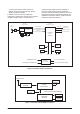
2. The Scorpio device, which contains an integral microprocessor and all GPS specific signal processing hardware. In addition, memory and other supporting components configure the receiver into a complete navigation system. Figure 1-3 illustrates an architecture that might be used to integrate a particular Jupiter receiver with an application processor that drives peripheral devices such as a display and keyboard.
2.0 Hardware interface Each binary message consists of a header portion and a data portion, each with its own checksum. Each message will have a header, but some messages may not have data. Message acknowledgements are in the form of a header, and message requests are also made using headers. Table 3-1 shows the data types used to define the elements of the binary interface messages.
independently for each message request. The user sets the request (R) bit and either the acknowledge (A) bit or negative acknowledge (N) bit, or both, to select the proper acknowledge behaviour. With this approach, the user can configure requests only to be NAKed, alerting the user when a problem arises without incurring the overhead necessary to continuously process ACKs. Figure 3-1 Binary message header format 3.
during the next output interval. Standard log requests will be accepted if the log (L) bit is set and if the required data parameters are present in the data portion of the request message. 3.2.5 Message header word 5 Word 5 of the message header is the data checksum, used to validate the header portion of the message. It is computed by summing (modulo 216) all words (including the word containing DEL and SOH) contained in the header and then performing a two’s complement on the sum.
The maximum number of characters in a sentence is 82, consisting of a maximum of 79 characters between the starting delimiter ‘$’ and the terminating and . Since the number of data fields can vary from sentence to sentence, it is important that the ‘listener’ (or application software) locate fields by counting delimiters rather than counting the total number of characters received from the start of the sentence.
Field Type Symbol Definition Special format fields Single character field: A = yes, data valid, warning flag clear V = no, data invalid, warning flag set Fixed/variable length field (degrees/minutes.decimal) two fixed digits of degrees, two fixed digits of minutes, and a variable number of digits for decimal-fraction of minutes Latitude 1111.
Output message name Message ID Geodetic position status output (*) 1000 Channel summary (*) 1002 Input message name Geodetic position and velocity initialisation User-defined datum definition Message ID 1200 1210 Visible satellites (*) 1003 Map datum select 1211 Differential GPS status 1005 Satellite elevation mask control 1212 Channel measurement 1007 Satellite candidate select 1213 ECEF position output 1009 Differential GPS control 1214 Receiver I D (**) 1011 Cold start control 12
3.5 Jupiter binary data messages This section describes the binary data messages of the Jupiter GPS receiver. All output and input binary messages are listed in Table 3-4 together with their corresponding message IDs. Power-up default messages are also identified. Binary messages are transmitted and received across the host port serial I/O interface (RS-232), default communication parameters are: 9600 bps, no parity, 8 data bits, 1 stop bit 3.5.
Word No 13 14 Name Non-DR link: polar navigation DR navigation link: Bit 0 = polar navigation Bit 15 to 1 = heading uncertainty standard deviation (Note 12) GPS week number Type Units Resolution 1 = true Bit Bit UI UI Range degrees weeks 1 = true 0 to 300 0 to 32 767 15-16 GPS seconds from epoch UDI s 0 to 604 799 17-18 GPS nanoseconds from epoch UDI ns 0 to 999 999 999 19 UTC day UI day 1 to 31 20 UTC month UI month 1 to 12 21 UTC year UI year 1980 to 2079 22 UTC hours
3.5.1.2 Message 1002 (channel summary) This message provides a summary form of the satellite range measurements and signal tracking information on a per- channel basis. The contents of the ‘channel summary’ message are described in Table 3-6 Message ID: 1002 Rate: Variable; defaults to 1 Hz Message Length: 51 words Word No.
3.5.1.3 Message 1003 (visible satellites) This message outputs the list of satellites visible to the receiver and their corresponding elevations and azimuths. The best possible DOPs, calculated from this visible list, are also provided. The contents of the ‘visible satellites’ message are described in Table 3-7. Message ID: 1003 Rate: Variable; default on update Message Length: 51 words Word No.
processed by the receiver. The contents of the ‘DGPS status’ message are described in Table 3-8. 3.5.1.4 Message 1005 (DGPS Status) This message contains DGPS status information derived from the last set of differential corrections Message ID: 1005 Rate: Variable Message Length: 25 words Word No. Name 1-4 Message header 5 Header checksum 6-7 Set time (Note 1) 8 Sequence number (Note 2) Type Units Range UDI 10 ms ticks 0 to 4 294 967 295 I 0 to 32 767 Status (9.0-9.15) 9.
3.5.1.5 Message 1007 (channel measurement) This message provides measurement and associated data for each of the receiver’s 12 channels. The contents of the ‘channel measurement’ message are described in Table 3-9. Message ID: 1007 Rate: Variable Message Length: 154 words Word No.
12 channels. The contents of the ‘channel measurement’ message are described in Table 3-10. 3.5.1.6 Message 1009 (reduced ECEF position status output) This message provides measurement and associated data for each of the receiver’s Message ID: 1009 Rate: variable Message length: 22 words Word No.
this message are also honoured. This message consists of five 20-byte (two characters per word), null-padded ASCII data fields. The contents of the ‘receiver ID’ message are described in Table 3-11. 3.5.1.7 Message 1011 (receiver ID) This message is output automatically at start-up after the receiver has completed its initialisation. It can be used to determine when the receiver is ready to accept serial input.
The contents of the ‘user settings output’ message are described in Table 3-12. 3.5.1.8 Message 1012 (user settings output) This message provides a summary of the settings for many of the user-definable parameters. Message ID: 1012 Rate: variable Message length: 22 words Word No. Name 1-4 Message header 5 Header checksum 6-7 Set time (Note 1) 8 Sequence number (Note 2) Type Units Range UDI 10 ms ticks 0 to 2 147 483 647 I Resolution 0 to 32 767 Operational status (9.0-9.15) 9.
3.5.1.9 Message 1100 (built-in test results ) This message provides detailed test results of the last BIT commanded since power-up. It is output automatically after the completion of a commanded BIT, but may also be queried manually as needed. Non-zero device failure status indicates failure. The contents of the ‘BIT results’ message are described in Table 3-13. Message ID: 1100 Rate: Variable Message Length: 20 words Word No.
400 milliseconds before the time mark pulse strobe signal. The contents of the ‘UTC time mark pulse output’ message are described in Table 3-14. 3.5.1.10 Message 1108 (UTC time mark pulse output) This message provides the UTC seconds into week associated with the UTC synchronised time mark pulse. This message is output approximately Message ID: 1108 Rate: 1 Hz Message length: 20 words Word No.
3.5.1.11 Message 1110 (frequency standard parameters in use) This message outputs the parameters used to support the receiver’s uncompensated crystal oscillator. The contents of the ‘frequency standard parameters in use’ message are described in Table 3-15. Note: Message 1110 is primarily used to output key parameters to GPS systems without non- volatile storage.
3.5.1.12 Message 1117 (power management duty cycle in use). This message controls the use of power management in the receiver. The contents of the ‘power management duty cycle in use’ message are described in Table 3-16. Message ID: 1117 Rate: Variable Message Length: 10 words Word No.
The contents of the ‘serial port communication parameters in use’ message are described in Table 3-17. 3.5.1.13 Message 1130 (serial port communication parameters in use). This message contains the communication parameters for the receiver’s two serial ports. Message ID: 1130 Rate: Variable Message Length: 21 words Word No.
Word No. Name Type Units Range Port 2 communication parameters (12.
configured for output on update (the default), as it will provide a notification of all stored configuration changes as they occur. The contents of the ‘EEPROM update’ message are described in Table 3-18. 3.5.1.14 Message 1135 (EEPROM Update). This message provides dynamic status notification for EEPROM writes. It contains the data block ID for the last set of data which was written to EEPROM.
in the status words indicate that those data blocks have been updated at least once in the EEPROM. The contents of the ‘EEPROM status’ message are described in Table 3-19. 3.5.1.15 Message 1136 (EEPROM status) This message provides failure and storage status information for the EEPROM. Bits set in the failure words represent write failures during attempts to update the corresponding blocks of data. Bits set Message ID: 1136 Rate: variable Message length: 18 words Word No.
3.5.1.16 Message 1160 (frequency standard table output data). This message contains parameters and table data used in the receiver’s frequency standard compensation model. It is intended that this message will be used in conjunction with Message 1360 to retrieve and restore this information for external storage. The contents of the ‘frequency standard table output data’ message are described in Table 3-20. Message ID: 1160 Rate: variable Message length: 270 words Word No.
3.5.1.17 Message 1180 (flash boot status). This message is output in the Jupiter flash board receiver only at start-up to control the flash download process and to report the results of the flash ROM checksum validation test. The contents of the ‘flash boot status’ message are described in Table 3-21. 3.5.1.18 Message 1190 (error/status) This message provides diagnostic information if the receiver encounters an error during execution of its firmware.
3.5.2 Binary input message descriptions. This section provides details for each of the input binary messages. 3.5.2.1 Message 1200 (geodetic position and velocity initialisation) This message allows the user to initialise the receiver with the specified geodetic position, ground speed, course over ground, and climb rate. The course may be either true or magnetic, as indicated by the magnetic course field.
use’ for the navigation function. Also, any message 1210 that contains an undefined datum code is ignored. 3.5.2.2 Message 1210 (user-defined datum) This message allows the user to define a datum to be used by the receiver to transform its position solution. Up to five user-defined datums may be stored. Storage of these parameters requires EEPROM. The contents of the ‘user-defined datum’ message are described in Table 3-24. Note that datum definition does not imply datum use.
3.5.2.4 Message 1212 (satellite elevation mask control). This message allows the user to set the elevation mask angle used by the receiver to select visible satellites. Storage of the Elevation Mask Angle parameter requires EEPROM. The contents of the ‘satellite elevation mask control’ message are described in Table 3-26. 3.5.2.5 Message 1213 (satellite candidate select). This message allows the user to construct the list of satellites which will be considered for selection by the receiver.
3.5.2.6 Message 1214 (DGPS control) This message allows the user to control the behavior of the receiver’s differential capability. Storage of this message’s parameters requires EEPROM. The contents of the ‘DGPS control’ message are described in Table 3-28. 3.5.2.7 Message 1216 (cold start control) This message allows the user to disable the cold start acquisition mode of the receiver. When cold start is enabled at power-on, the cold start timer is set to 0.
3.5.2.8 Message 1217 (solution validity input) The receiver will always output the best position solution it can attain, depending on the number and quality of available measurements. The Solution Validity Input Message allows the user to define the criteria for setting the position validity status specified in the position output messages. The status will be set to ‘invalid’ if any of the specified requirements are not met. Storage of this message’s parameters requires EEPROM.
3.5.2.9 Message 1219 (user-entered altitude input). This message allows the user to enter an altitude to be used for altitude hold during 2D navigation. If the ‘force use’ field is not set, the receiver may ignore the altitude input if it thinks it has a better estimate. Setting the ‘clear’ field will clear out the last estimate of altitude which the receiver uses for altitude hold. Setting the ‘MSL select’ field allows entry of mean-sea- level altitude.
application in which the receiver is being used. Storage for the Platform parameter requires EEPROM. The contents of the ‘application platform control’ message are described in Table 3-32 3.5.2.10 Message 1220 (application platform control). This message allows the user to adjust the receiver’s dynamics based on the type of Message ID: 1220 Rate: as required (maximum rate is 1 Hz) Message length: 8 words Word No.
3.5.2.11 Message 1221 (nav configuration). This message allows the user to control various features in the navigation processing. The held altitude disable bit controls the use of stored GPS-based altitude to aid the receiver when the vertical geometry deteriorates. The ground track smoothing bit controls the use of satellite range bias estimates to minimise the position shifts resulting from SA and constellation changes.
3.5.2.13 Message 1303 (restart command). This message commands a full restart each time it is received. The contents of the ‘restart command’ message are described in Table 3-35. Message ID: 1303 Rate: as required (maximum rate approximately 0.2 Hz) Message length: 8 words Word No. Name 1-4 Message header Type Units Range 5 Header checksum 6 Sequence number (Note 1) 7.0 Invalidate RAM (Note 2) 7.1 Invalidate EEPROM (Note 3) Bit 0 to 1 7.
3.5.2.14 Message 1310 (frequency standard input parameters). This message defines the temperature polynomial, coefficients, and scale factors used by the receiver’s frequency standard compensation model. The contents of the ‘frequency standard input parameters’ message are described in Table 3-36. Note: Message 1310 is primarily used to input key parameters from GPS systems without non-volatile storage. This is why the format of output Message 1110 is exactly the same.
3.5.2.15 Message 1317 (power management control). This message controls the use of power management in the receiver. The contents of the ‘power management control’ message are described in Table 3-37. Note: Message 1317 is primarily used to input key parameters from GPS systems without non-volatile storage. This is why the format of output message 1117 is exactly the same. In other words, the output message is used to capture data while the input message is used to restore data.
3.5.2.16 Message 1330 (serial port communication parameters). This message allows the user to set the communication parameters for the receiver’s two serial ports. The contents of the ‘serial port communication parameters’ message are described in Table 3-38. Message ID: 1330 Rate: As required (maximum rate 1 Hz) Message Length: 20 words Word No. Name 1-4 Message header Type 5 Header checksum 6 Sequence number (Note 1) I Units Range 0 to 32 767 Port control/validity data 7.
3.5.2.17 Message 1331 (message protocol control) This message allows the user to set the message format protocol which will be used to communicate information to and from the receiver through the host serial I/O port. Currently, the available protocols are binary (with fixed-point numbers) and NMEA-0183. Storage for the protocol type parameter requires EEPROM. The contents of the ‘message protocol control’ message are described in Table 3-39. 3.5.2.18 Message 1350 (factory calibration input).
3.5.2.19 Message 1351 (raw DGPS RTCM SC-104 data) This input message contains DGPS RTCM SC-l04 data. The message is provided for backwards compatibility with the earlier MicroTracker GPS receiver and may be used in lieu of the auxiliary port data. The contents of the ‘raw DGPS RTCM SC-l04 data’ message are described in Table 3-41. Message ID: 1351 Rate: As required. The maximum allowable rate is once every 100 ms (Note 1) Message Length: Varies with message Word No.
3.5.2.20 Message 1360 (frequency standard table input data). This message allows the user to input the parameters and table data used in the receiver’s frequency standard compensation model. It is intended that this message will be used in conjunction with message 1160 to retrieve and restore this information for external storage. The contents of the ‘frequency standard table input data’ message are described in Table 3-42. 3.5.2.21 Message 1380 (flash reprogram).
3.6 Jupiter NMEA data messages Output message name Message ID This section describes the NMEA data messages of the Jupiter GPS receiver. All of the output and input NMEA messages are listed in Table 3-44 together with their corresponding message IDs. Power-up default messages are also identified. Navman proprietary built-in test results BIT Navman proprietary error/status ERR NMEA mode is selected according to the logic described in the appropriate ‘Jupiter’ reciever data sheet.
3.6.1.2 Navman proprietary error/status (ERR) This message provides diagnostic information if the receiver encounters an error during execution of its firmware. The contents of the ‘ERR’ message are described in Table 3-46. Sample message: $PRWIERR,0,0,005BC9*0l navigation solution passes all validity criteria (set using the binary ‘solution validity criteria’ message), a GGA message is generated automatically. If any of the validity criteria are invalid for the solution, a GGA message is not generated.
5.6.1.4 GPS satellites active and DOP (GSA) . This message contains the Jupiter receiver’s operating mode, satellites used for navigation, and DOP values. The contents of the ‘GSA’ message are described in Table 3-48. Sample message: $GPGSA,A,3,04,16,09,24,,,,,3.33,1.96,2.70* 06 and Signal-to-Noise Ratio (SNR) values. Each transmission identifies up to four satellites (max); additional satellite data is sent in a second or third message.
3.6.1.6 Navman proprietary receiver ID (RID) This message is output automatically at startup (after receiver initialisation is complete), it can also be requested manually. It can be used to determine when the receiver is ready to accept serial input. The contents of the ‘RID’ message are described in Table 3-50. Sample message: $PRWIRID,12,00.90,12/25/95,0003,*40 Message ID: RID Rate: variable (see above) Fields: 5 Field No.
3.6.1.7 Recommended minimum specific GPS data (RMC) This message contains time, date, position, course, and speed data. The fields in this message always contain data even when the receiver is not navigating. This allows user-initialised, stored, or default values to be displayed before a solution is obtained. The contents of the ‘RMC’ message are described in Table 3-51. Sample message: $GPRMC,185203,A,3339.7332,N,11751.7598, W,0.000,121.7,160496,13.
3.6.1.8 Course over ground and ground speed (VTG). This message contains the course over ground (true and magnetic) and speed relative to the ground. The contents of the ‘VTG’ message are described in Table 3-52. Sample message: $GPVTG,291.3,T,277.3,M,0.784,N,1.452,K*4F Message ID: VTG (while receiver is in navigation mode -- Note 1) Rate: Variable Fields: 8 Field No.
3.6.1.9 Navman proprietary Jupiter channel status (ZCH). This message complements the GSV message by providing satellite-to-channel mapping and a status indication for each channel. The contents of the ‘ZCH’ message are described in Table 3-53. Sample message: $PRWIZCH,05,F,20,F,04,F,09,F,16,F,06,F,07,6, 00,0,24,F,00,0,00,0,00,0*37 Message ID: ZCH Rate: variable; defaults to 1 Hz Fields: 24 Field No.
3.6.2 NMEA input message descriptions. This section provides details for each of the input NMEA messages. 3.6.2.1 Navman proprietary built-in test command message (IBIT). This proprietary message instructs the receiver to immediately execute its BIT. Results of the BIT are available in the Navman proprietary BIT results message. The data field is reserved and should be left null. The contents of the ‘IBIT’ message are described in Table 3-54. Sample message: 3.6.2.
3.6.2.3 Navman proprietary receiver initialisation message (INIT). This proprietary message commands the Jupiter receiver to perform a reset, modify its operating mode, or reinitialise itself using specified parameters. The contents of the ‘INIT’ message are described in Table 3-56. Sample message: $PRWIINIT,V,3339.650,N,11751.680,W,64.131, 0.0,M,0.0,T,162338,190594 Message ID: INIT Rate: as required Fields: 14 Field No.
3.6.2.4 Navman proprietary protocol message (IPRO). 3.6.2.5 Standard query message (Q). This proprietary message allows the user to set the message format protocol which will be used to communicate information to and from the receiver through the host serial I/O port. Currently, the available protocols are binary (with fixedpoint numbers) and NMEA-0183. Storage for the protocol type parameter requires EEPROM. The contents of the ‘IPRO’ message are described in Table 3-57.
4.0 Jupiter GPS receiver operation This section presents a detailed operational description of the Jupiter series of GPS receivers. An overview is provided for the navigation and receiver support functions. Each of the receiver’s internal storage devices are described as well as how each one is initialised and used to control operational configurations. This section also provides a description of start-up modes and satellite management. 4.
4.3 Configuration 4.3.1 Definition Configuration is defined as the set of data or actions that provide information that is fairly constant and usually connected with installation, environmental, or user preferences. Common examples are map datums or satellite elevation mask angle. Configuration data customises or optimises the GPS receiver for use in a particular situation. In general, this data is held constant until the user decides to change it.
4.3.4 Differential GPS (DGPS) control Jupiter GPS DGPS operation: disable and correction timeout. When DGPS disable is asserted, the navigation solution is computed without the benefit of differential corrections even if they are available. The DGPS timeout parameter is used to specify the maximum allowable time difference between current time and the validity time of the DGPS corrections.
used to identify previously healthy satellites and to generate “working” visible satellite lists, while frequency standard data minimises satellite acquisition uncertainties. 4.4.4 Frozen start This state is entered if there are no valid data sources available (SRAM, RTC, EEPROM). This is considered to be a recovery mode because EEPROM should always contain valid information.
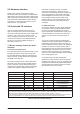
GDOP. The DOP fields in message 1003 are set to maximum values when GDOP cannot be computed. 4.5.2 Acquisition modes Two methods of satellite acquisition are used by the Jupiter GPS receiver: sequential acquisition and parallel acquisition. 4.5.2.1 Sequential acquisition Sequential acquisition describes the acquisition of a satellite with all non-tracking channels.
Figure 4-1 Jupiter search process MN002000A © 2004 Navman NZ Ltd. All rights reserved. Proprietary information and specifications subject to change without notice.
4.6 Navigation This section describes the operation of the navigation software in the GPS receiver. It defines many of the features of the navigation system with emphasis on those that the OEM can control. The navigation software initialises and maintains a state vector which is used to report time, position, and velocity to the user. The navigation software uses pseudo-range, integrated carrier phase, and Doppler measurements from the satellites, and external altitude inputs if available.
4.6.2 Platform class The Jupiter GPS receiver supports three platform classes: pedestrian (low dynamics automotive (medium dynamics) aircraft (high dynamics) The platform class is set by the OEM to optimise navigation processing for the dynamics of the specific platform that is carrying the receiver. The class is used to set process noise parameters, velocity decay time constants, and speed and altitude limits. The default platform class is automotive.
These errors induce velocities in the receiver’s state estimate even if the receiver is motionless. The magnitude of these velocities depends on the geometry and number of satellites in track. Typical values are between one-half and two metres per second. The position estimate of the receiver will vary within a circle of approximately 100 m (the 2Drms position error specified in the GPS SPS Signal Specification).
If the measurements are lost for a long time, the EHPE and EVPE will grow until they surpass their thresholds and the solution fails the validity test for that reason. Some applications require a solution to be marked invalid unless it uses three, four, or more satellites. The OEM can set any of these thresholds by sending a binary ‘solution validity criteria’ message (Message 1217) with the number of satellites required 4.6.4.4.
update. The various parameters and data maintained in the Jupiter receiver’s EEPROM are listed in Table 4-2. communications protocol, and message controls are stored in non-volatile EEPROM. 4.7.1.2 The auxiliary port The auxiliary port is used exclusively for the receipt of differential corrections in RTCM SC-I04 serial message format. By default, the auxiliary port is configured for 9600 baud, no parity, 8 data bits, and 1 stop bit. There is no data output from this port. 4.7.
measurements before computing a position solution. This technique effectively eliminates much of the error due to SA as well as errors due to unmodelled satellite clock errors, satellite ephemeris errors, and atmospheric delays. This ‘improved’ solution is present in all output messages. With a few minor exceptions outlined below, DGPS is enabled by default, but may be disabled by the OEM. Because SA changes with time, the corrections deteriorate with time as well.
Ephemeris data has been collected by the receiver for at least four satellites. DGPS corrections have been received for at least the same four satellites, and these corrections are not older than the time limit specified in the Differential GPS Control message (binary Message 1214) The Issue Of Data Ephemeris (lODE) is the same for both the receiver-collected ephemeris and the RTCM SC-I04 corrections.
access it. A failed status means that the EEPROM chip may be defective. Digital Signal Processor (DSP) The DSP failure word in message 1100 indicates the results of the DSP tests. A failed status indicates that one or more of the DSP tests failed and that the DSP chip may be defective. RTC The RTC failure word in message 1100 indicates the results of a time rollover test of the RTC. A failed status indicates that the RTC test failed and that the RTC chip may be defective.
Appendix A: Acronyms, abbreviations, and glossary support GPS development and testing. A total of 10 Block I satellites were successfully launched between February 1978 and October 1989. This appendix provides a list of all acronyms, abbreviations, and selected terms used in this document, together with their associated meaning. Block II satellite: satellites designed and built to support GPS ‘Space Segment’ operation. A total of 28 Block II satellites had been built and launched as of August 1995.
GPS accuracy that uses pseudo-range errors recorded at a known location to improve the measurements made by other GPS receivers within the same general geographic area. GPS receiver solution. The lower the value of the GDOP parameter, the less the error in the position solution. Related indicators include PDOP, HDOP, TDOP, and VDOP. DI: Double Precision Integer. GMT: Greenwich Mean Time.
km: Kilometre. L1 Band: the 1575.42 MHz GPS carrier frequency which contains the C/A code, P-code, and navigation messages used by commercial GPS receivers. L2 Band: a secondary GPS carrier, containing only P-code, used primarily to calculate signal delays caused by the ionosphere. The L2 frequency is 1227.60 MHz. the measurements from all GPS satellites it can track, instead of the four necessary for a threedimensional position solution.
RTCA: Radio Technical Commission for Aeronautics. RTCM: Radio Technical Commission for Maritime Services. SA: Selective Availability. The method used by the DoD to control access to the full accuracy achievable with the C/A code. Satellite elevation: the angle of the satellite above the horizon. SEP: Spherical Error Probable.
Appendix B: References This appendix provides a list of documents that may help a user of Navman’s GPS receivers to learn more about the way the GPS can be used. Not all of these documents have been referred to in the text of this document. 1. Global Position System Standard Positioning Service Signal Specification, United States Department of Defense. 2. Standard For Interfacing Marine Electronic Devices, NMEA 0183, National Marine Electronics Association. 3.
as antennas and processors. This equipment allows users to receive, decode, and process the information necessary to obtain accurate position, velocity, and timing measurements. This data is used by the receiver’s support equipment for specific application requirements. GPS supports a wide variety of applications including navigation, surveying, and time transfer. Receivers may be used in a stand-alone mode or integrated with other systems to enhance the overall system performance.
Figure C-3 Satellite ranging intersections Similar equations are then used to calculate velocity using relative velocities instead of pseudoranges. The position, velocity, and time data is generally computed once a second. If one of these parameters, such as altitude, is known, only three satellite pseudo-range measurements are needed for the receiver to determine its position and time. In this case, only three satellites need to be tracked.
reserved for use by the DoD and certain authorised users. SPS is less accurate and intended for general public use. This is the level of accuracy used by the Jupiter family of GPS receivers. The SPS signal can be intentionally degraded to a certain extent by a process known as Selective Availability (SA). SA is used to limit access to the full accuracy of SPS in the interest of D.S. national security.
Occasionally a type 2 message is sent interspersed among the correction messages, which provides a secondary correction. This is done to allow a user to operate with old (up to two hours) satellite ephemeris and satellite clock data while the reference station is operating with most recent data. This correction, called the ‘delta correction’ is added to the normal correction for that satellite.
APPENDIX D: Frequently Asked Questions (FAQ) This appendix provides answers to frequently asked questions about GPS in general and about the Jupiter series of GPS receivers, it is intended to supplement the operational description provided in section 4.0 of this document. 1. How far and under what conditions can a passive antenna track before it is necessary to change it to an active antenna? There is no simple answer to this question.
APPENDIX E: Reference ellipsoids and datum tables for Jupiter and NavCore receivers Reference Ellipsoids The following data is taken from DoD World Geodetic System 1984, DMA TR 8350.2-B, 1 Dec 1987, Second Printing. Includes 1 Sept 1991 updates. REFERENCE ELLIPSOIDS No. Name Semi-Major Axis Inverse Flattening 1 Airy 6377563.396000 299.324965 2 Modified Airy 6377340.189000 299.324965 3 Australian National 6378160.000000 298.250000 4 Bessel 1841 6377397.155000 299.
The following lists of datums, maintained and selectable through the LABMON development software, apply to Navman’s Jupiter Series of GPS receivers.
Code Ell dx dy dz 38 Canton Astro 1966 - Phoenix Islands 15 298 304 –375 39 Cape - South Africa 6 –136 108 –292 40 Cape Canaveral - Bahamas, Florida 5 -2 151 181 41 6 –263 6 431 15 175 –38 113 43 Carthage - Tunisia Chatham Island Astro 1971 New Zealand (Chatham Island) Chua Astro - Paraguay 15 –134 229 –29 44 Corrego Alegre - Brazil 15 –206 172 –6 45 Dabola - Guinea Djakarta (Batavia) Indonesia (Sumatra) DOS 1968 New Georgia Islands (Gizo Island) Easter Island 19
Code Ell dx dy dz 74 Indian - Bangladesh Name 7 282 726 254 75 Indian - India, Nepal 23 295 736 257 76 Indian 1954 - Thailand, Vietnam 7 218 816 297 77 Indian 1975 - Thailand 7 209 818 290 78 2 506 –122 611 15 –794 119 –298 80 Ireland 1965 - Ireland ISTS 061 Astro 1968 South Georgia Islands ISTS 073 Astro 1969 - Diego Garcia 15 208 –435 –229 81 Johnston Island 1961 - Johnston Island 15 189 –79 –202 82 7 –97 787 86 15 145 –187 103 84 Kandawala - Sr
Code 116 Name North American 1927 Canada (Alberta, British Columbia) North American 1927 Canada (Manitoba, Ontario) North American 1927 Canada (New Brunswick, Newfoundland, Nova Scotia, Quebec) North American 1927 Canada (Northwest Territories, Saskatchewan) North American 1927 - Canada (Yukon) 117 North American 1927 - Canal Zone 5 0 125 201 118 5 –9 152 178 5 11 114 195 5 –12 130 190 12 0 0 0 12 0 0 0 15 –425 -169 81 13 –130 110 –13 5 61 –285 –181 126 North Ameri
Code Ell dx dy dz 145 Provisional S. American 1956 - Colombia 15 –282 169 –371 146 Provisional S. American 1956 - Ecuador 15 –278 171 –367 147 Provisional S. American 1956 - Guyana 15 –298 159 –369 148 15 –279 175 –379 15 –295 173 –371 15 16 196 93 5 11 72 –101 152 Provisional S. American 1956 - Peru Provisional S. American 1956 Venezuela Provisional S.
0 WGS-84 (Default) 49 Mahe 1971 1 Adindan 50 Marco Astro 2 AFG 51 Massawa 3 AlN EL ABD 1970 52 Merchich 4 Anna 1 Astro 1965 53 Midway Astro 1961 5 ARC 1950 54 Minna 6 ARC 1960 55 Nahrwan Masirah Island 7 Ascension Island 1958 56 Narhwan United Arab Emirates 8 Astro Beacon “E” 57 Nahrwan Saudia Arabia 9 Astro B4 SOR.
APPENDIX F: 2 x 10 pin field connector information This appendix contains ordering information for the 2 x l0 pin field connector. Note: The Pico modules have a different 2 x 10 pin field connector to the one described below.
*Teflon is a trademark of DuPont © 2004 Navman NZ Ltd. All Rights Reserved. Information in this document is provided in connection with Navman NZ Ltd. (‘Navman’) products. These materials are provided by Navman as a service to its customers and may be used for informational purposes only. Navman assumes no responsibility for errors or omissions in these materials. Navman may make changes to specifications and product descriptions at any time, without notice.