www.navman.com Pilot 3380 Tracker 5505/5605 C H A RA TU PT LO O P T I T L E O R T Installation and Operation Manual NAVMAN www.Busse-Yachtshop.de email: info@busse-yachtshop.
! CAUTION IMPORTANT SAFETY INFORMATION Please read carefully before installation and use. ! WARNING DANGER ! CAUTION This is the safety alert symbol. It is used to alert you to potential personal injury hazards, Obey all safety messages that follow this symbol to avoidpossible injury or death.
Important It is your sole responsibility to install and use Navman’s instrument and GPS antenna in a manner that will not cause accidents, personal injury or property damage. Always observe safe boating practices. The choice, location, angle and installation of the instrument & GPS antenna are critical to performance of the system as intended. Follow instructions in this manual carefully. If in doubt, consult your Navman dealer.
Contents 1 Introduction ..........................................................................................................................................7 1-1 Overview . . . . . . . . . . . . . . . . . . . . . . . . . . . . . . . . . . . . . . . . . . . . . . . . . . . . . . . . . . . . . . . . . . . . . . . . . 7 1-2 Cleaning and maintenance . . . . . . . . . . . . . . . . . . . . . . . . . . . . . . . . . . . . . . . . . . . . . . . . . . . . . . . 7 1-3 Plug-in cards . . . . . . . . . . . . . .
10 Fuel functions and display .................................................................................................................. 31 10-1 What the fuel computer does . . . . . . . . . . . . . . . . . . . . . . . . . . . . . . . . . . . . . . . . . . . . . . . . . . 31 10-2 Fuel display . . . . . . . . . . . . . . . . . . . . . . . . . . . . . . . . . . . . . . . . . . . . . . . . . . . . . . . . . . . . . . . . . . . . 31 10-3 When you add or remove fuel . . . . . . . . . . . . . . . . . . .
Appendix A - Specifications .....................................................................................................................60 Appendix B - Troubleshooting .................................................................................................................62 Appendix C - Glossary and navigation data ..............................................................................................
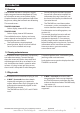
1 Introduction 1-1 Overview The NAVMAN TRACKER is a compact, rugged, highly integrated marine chartplotter. It is easy to use and has an easy to read colour display. Complex functions can be performed with a few key presses, taking the hard work out of boating. SmartCraft engine functions require a SmartCraft system to be installed. For information on using SmartCraft, see the SmartCraft Gateway Installation and Operation Manual.
DANGER Changing the plug-in card CAUTION Handle plug-in cards carefully. Keep them in their protective cases when not plugged into the TRACKER. Keep the holder in place in the TRACKER at all times to prevent moisture from entering the card compartment. Gold contacts under here 1 3 2 4 Card Holder Turn the TRACKER off (see section 2-2). Pull the card holder out of the TRACKER and pull any card out of holder. Put the card in its case. Push new card into holder.
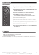
2 Basic Operation Overview of the keys 1) 2) 1) Go back to an earlier menu or display. Any changes made are ignored. In chart mode, centres chart at boat’s position. 2) Show a menu of the main displays. To go to a display, select it from the menu (see section 2-8). 3) 4) 5) 6) 7) 3) Cursor keys, to move the cursor or the selection highlight. 4) Show a menu of the options for the current display. Press again to display the Setup menu (see section 14). 5) Start an action or accept a change.
2-2 Using the menus Operate the TRACKER by selecting items from menus. Items can be submenus, commands or data. Selecting a submenu A after a menu item indicates a submenu, for example Chart . Press or to move the highlight to the submenu, then press . Starting a command Press or to move the highlight to the command, for example Goto cursor, then press . c) To change a name or number: 1 Press 2 Press or to select a letter or digit to change. Press or to change the letter or digit.
2-4 Backlight and night mode To go to the Backlight display, press briefly. When you have finished, press . Night mode Night mode sets the palette for all displays. Backlight Normal palette, for daytime The display and keys are backlit. To change the backlight level, select Backlight, then press to dim or to brighten. A palette optimised for night time. To change mode, select Night mode, then press . To change only the chart palette, see section 14-2.
2-7 Simulate mode In Simulate mode, the TRACKER ignores data from the GPS antenna and other transducers and sensors and the TRACKER generates this data itself. Otherwise, the TRACKER functions normally. There are two simulate modes: Normal: Allows a user to become familiar with the TRACKER off the water. Demo: Simulates a boat moving along a route and automatically displays different TRACKER functions. To start and stop Simulate mode, and for more information, see section 14-11.
Other menu and displays Note: Press to go from an Other display back to your last chart display. TRACKER 5505/5505i/5605 Installation and Operation Manual www.Busse-Yachtshop.de NAVMAN email: info@busse-yachtshop.
2-8-1 Dual displays If Chart is the active display: press to display the options for Chart; press twice to make Gauges the active display. The TRACKER can show two displays at once, for example Chart + Gauges. One of the displays, called the active display, has a yellow border and is controlled by the user. To change the active display, press twice (Highway cannot be the active display).
Tip: If less than the maximum number of lines of data are used, the data will take up less of the display area. 5 Press to return to the display. 2-8-3 Compass The chart and highway displays can show a compass at the top of the display. To turn the compass off or on: The compass always shows the boat’s course over ground (COG), a red symbol in the middle. When the boat is navigating to a point, the compass also shows bearing to the destination (BRG), a black symbol.
3 Navigation: Chart The chart display shows the chart, the boat’s position course and navigation data. 3-1 Overview of navigating The TRACKER has two ways of navigating, going straight to a point or following a route. 3-1-1 Navigating to a point D When the TRACKER is navigating to a point, the chart and highway displays show navigation data: A The boat position . B The destination point marked with a circle. C The boat’s plotted course to the destination.
Going to a point on the chart Navigating 1 Switch to a chart display. 2 Move the cursor to the destination point: either use the cursor keys or use Find (see section 3-2-5). The TRACKER navigates to the point as described in section 3-1-1. 3 Press Cancelling navigating Go to a Chart display, press Cancel goto. ! and CAUTION select Goto cursor. ! and select WARNING Make sure the course does not pass over land or dangerous waters.
3-2 Chart display To go to the Chart display, press , select Chart, then select Chart. A typical chart display shows: A B C D K E J F I H G A Data header. To turn the data off or on or to change what data is displayed, see section 2-8-2 B Compass (see section 2-8-3) C Chart scale (see section 3-2-3) D Boat position (see section 3-2-1) E Boat track (see section 3-5) F Boat course and CDI lines (see Appendix C, CDI).
3-2-1 Chart modes The Chart has two modes: Press midway between two of the cursor keys to make the cursor move diagonally. Centre on boat mode Hold a cursor key down to make the cursor move continuously across the display. To switch to centre on boat mode in the chart display, press . The boat is at the centre of the chart. As the boat moves through the water, the chart automatically scrolls to keep the boat in the centre of the chart. The cursor (see below) is turned off.
3-2-5 Finding a chart symbol To find and display a chart symbol: Press 2 Select the type of symbol: Waypoints, Routes, Ports by name, Ports & services, or Tide stations. 3 For Ports & services: select the type of service to find. For Ports by name: press , , or to enter a name or letters contained in the port name, then press . 4 For Ports by name: to search for a different port name, press . change the name, then press . and select Find. 1 A list of items is displayed.
3-4 Projected course If Projected course is turned on, then the TRACKER will display the projected position based on the course over ground (COG), speed and a specified time. To turn Projected course on and off and to set the time, see section 14-2.
4 Navigation: Highway display The highway display has a bird’s eye view of the boat’s course to a destination. To go to the Highway display, press , select Other, then select Highway. A B The highway display shows: C A Optional data header (see section 2-8-3) B Optional compass (see section 2-8-4) C Destination waypoint D Boat’s plotted course to destination D E E CDI lines, parallel to the boat’s plotted course (see Appendix C, CDI).
5-1 Waypoints display To go to the waypoints display, press , select Other, then select Waypoints. The waypoints display is a list of the waypoints that have been entered, each with waypoint symbol, name, latitude and longitude, distance and bearing from the boat, type and display option. If there are more waypoints than will fit on the display, press or to scroll up or down a page at a time.
5-2-3 Editing a waypoint Editing a waypoint from the waypoints display Editing a waypoint from the chart display 1 In the chart display, move the cursor to the waypoint to edit. 1 and select Edit. 2 Press 3 Change the waypoint data (see section 5-2-7). Select Save. 2 In the waypoints display, press or to highlight the waypoint to edit. Press and select Edit. Change the waypoint data (see section 5-2-7). Select Save.
5-2-8 Sort Waypoints Icon: Grouped by icon type. To change how the waypoints list is displayed: Distance: In order of distance from the boat. An arrow at at the top of a column indicates how the waypoints are sorted. and select Sort by. 1 Press 2 Select how to display the list: Name: In alphabetical order by name. 5-2-9 Navigating to a waypoint See section 3-1-2. 6 Navigation: Routes A route is a list of waypoints that the boat can navigate along. Routes can be created, changed and deleted.
6-2 Managing !routes CAUTION ! 2 WARNING After creating or changing a route, display the route on the chart and check that it DANGER does not cross land or dangerous water. 6-2-1 Creating CAUTION a new route While creating the route: and select Insert. . To move a waypoint in the route: Move the cursor to the waypoint to move. ii Press A data box at the bottom left of the display shows the route name and total distance.
4 To insert a waypoint in the route: i automatically. If the route has more waypoints than will fit on the display, press or to see them. Select where the waypoint will be: To insert the first waypoint in a new route, select Leg 1. 5 To insert a waypoint at the end of the route, select the unused leg at the end of the list of waypoints. Otherwise, select the waypoint to insert the new waypoint in front of. ii Press . A list of waypoints is displayed. Select the waypoint to use.
7 Satellites GPS worldwide navigation The US Government operates the GPS system. Twenty-four satellites orbit the earth and broadcast position and time signals. The positions of these satellites are constantly changing. The GPS receiver analyses the signals from the closest satellites and calculates exactly where it is on earth. This is called the GPS position. The accuracy of the GPS position is typically better than 10 m (33 ft) for 95% of the time.
7-1 Satellite display A Status of GPS antenna, for example Acquiring, GPS fix, No GPS. If the unit is in Simulate mode it displays Simulate (see section 2-7) The satellite display shows: B Time and date from GPS satellites. Time is local time (UTC [GMT] plus local offset, see section 14-10) A C HDOP: The error in the GPS position caused by satellite geometry.
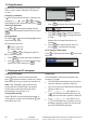
Changing the Gauges display 1 Go to the Gauges display and press 2 To select the gauge type. i ii 3 . Select Gauge type. Select Analog (round) or Digital (numbers). To change the data displayed: i ii Select Gauge setup. Change a gauge: a) Press the cursor keys to highlight the gauge. b) Press items. to display a menu of data c) Select a data item that is available on your system. iii Repeat the above step to set the other gauges. Press . 4 Press to return to the Gauges display.
10 Fuel functions and display The Fuel functions require optional petrol/gasoline, diesel or SmartCraft fuel sensors to be installed and set up. 10-1 What the fuel computer does Each engine has a flow sensor installed to measure the engine’s fuel flow. The TRACKER uses these flows, together with boat speed and engine RPM if available to estimate the fuel remaining in the tank(s), fuel used, range and fuel economy. This data is displayed on the fuel display (see section 10-2).
Fuel display without engine RPM Fuel display with engine RPM Range The estimated boat range at the current fuel flow. The value can depend on the type of speed sensor (see section 10-5). Economy The distance travelled per unit of fuel used. The value can depend on the type of speed sensor (see section 10-5). The larger the value, the better the fuel economy. Adjust the throttle and trim to achieve the best economy.
Note: If you follow procedure B every time you add fuel, then a small error will accumulate, because it is hard to measure exactly how much fuel you add. To avoid this, completely fill the tank and follow procedure A about every tenth time you add fuel. 4. Remove fuel from the tank and write down how much fuel you remove. C When you remove fuel 6. Change the number on the Set Remaining menu to the amount of fuel that you calculated was now in the tank. 5.
10-5-2 Water speed and ground speed A paddlewheel sensor and a pitot sensor measure water speed, the boat speed through the water. A GPS measures ground speed, the boat speed over the bottom of the water. If there is a current, then these speeds will be different, and the log, trip log, economy and range will be different, as shown below. Water speed is better for measuring the boat’s potential performance, Ground speed is better for going to a destination because it takes currents into account.
10-6 Fuel consumption curves A fuel consumption curve shows fuel consumption (fuel used per unit of distance travelled) and boat speed as a function of engine RPM. Fuel consumption curves require engine RPM, which requires SmartCraft or diesel sensors to be installed. Fuel consumption curves are powerful tools for assessing boat performance in different conditions and for helping you to run at the most economical speed for the conditions.
10-6-2 Managing fuel consumption curves Renaming a curve 1 2 3 Press one or more times until the Setup menu is displayed, then select Fuel. Select Fuel consumption curve. Select Name and select the name of the curve to rename. Select Rename and press the name. . Change Using a curve Compare your boat’s performance now, at the current RPMs, with the boat’s performance when you made the curve.
10-7 Calibration Calibrate petrol/gasoline fuel flow sensors during installation, or if the fuel readings seem inaccurate and the other troubleshooting suggestions do not help (see appendix B troubleshooting). To calibrate the sensor(s): Note SmartCraft fuel sensors and Navman diesel sensors are factory calibrated and should never need recalibrating. On a multi engine boat, calibrate each engine’s sensor.
11 Tides display The tides display is available on C-MAP charts. The tides display shows tide information at a tide station for the selected date. 3 A list of tide stations are displayed. Select the tide station to display. The chart redraws with the tide station centred. Note: The tides display requires the local time offset to be set to work correctly (see section 14-10) 4 Press 5 Select Tide height.
12 User card display A C-MAP™ user card is an optional plug-in card that can store data files (see section 1-3). There are three types of files: waypoints, routes or a track. To go to the user card display, press select Other, then select User card. , Note: 1 Before using a user card, remove any chart card and plug the user card in. When you have finished with the user card, remove the user card and replace the chart card (see section 1-3). 2 The older 5 volt cards are not supported.
A routes file: The new routes are added to any existing routes in the TRACKER. If a new route has the same name as an existing route but has different data then the TRACKER asks which route to keep. Formatting the user card A track file: The new track will replace the existing track in the TRACKER. 1 Press 2 Select Format. To load a file to the TRACKER: 1 Select the file to load. 2 Press 3 and select Load. Deleting a file from the user card 1 Select the file to delete.
14 Setting up the TRACKER The TRACKER has a number of advanced features which are set up through the setup menu. We recommend that you become familiar with the operation of the unit using the default settings before making any changes to the data in these menus. To go to a setup option menu, press one or more times to display the setup menu, then select an option. Note: 1 The Setup menu options are explained in the following sections. 2 Section 2-1 describes how to set or change data in the setup menus.
Setup option menus Factory default settings are shown. The setup data available will depend on the optional sensors and instruments installed. System (see 14-1) Chart (see 14-2) Water (14-2) Land Others (14-2) Fuel (see 14-4) GPS (see 14-3) SmartCraft (see the SmartCraft Gateway Installation and Operation Manual) Track (see 14-5) Comms (see 14-9) 42 Logs (see 14-6) Time (see 14-10) NAVMAN www.Busse-Yachtshop.
Factory reset This option returns all of the TRACKER settings (except the language, waypoints and routes) to the default factory settings shown on the setup menus. SmartCraft No SmartCraft gateway is fitted. Disable SmartCraft functions. Normal SmartCraft operation See section 15-8. 14-2 Setup > Chart Press once or more until the Setup menu is displayed, then select Chart: Rotation The options for chart rotation are: North up: North is always at the top of the chart display.
Map shift Setting map datum In the Chart setup menu, select Map datum. 1 2 Select the map datum for the paper chart you are using. 3 ! WARNING Latitude and longitude coordinates displayed on any NMEA repeaters match the coordinates on the TRACKER. However, latitude and longitude coordinates broadcast on any NMEA VHF transmitter will be slightly offset from coordinates on a WGS 84 chart.
General submenu Plotter mode Normal: only scales available on the chart card can be displayed. If you press or to select a chart scale which is not available, on the chart card, the chart display will change to this scale but will only display the boat position and track (if enabled). The rest of the display is white with black crosshatch lines and no chart information is displayed. This is useful to zoom to a small scale to track small boat movements or if there is no detailed chart for an area.
14-3 Setup > GPS Press once or more until the Setup menu is displayed, then select GPS: Static Navigation When the boat stops or moves very slowly, the calculated GPS speed and course become erratic. Static navigation is a number, and the options are: • 0.01 to 99.9:If the boat speed is slower than this, the speed is displayed as zero and the course stays unchanged. • 0(Off): The calculated speed and course are always used.
14-4 Setup > Fuel Fuel functions require optional fuel flow sensors to be installed. Press one or more times until the Setup menu is displayed, then select Fuel: The Flow filter can be set from 0 to 30 seconds. Use the lowest value which gives a stable flow. Usually a value of 5 to 10 seconds will give a satisfactory result for two-stroke carburettor engines. Fuel injected or four-stroke engines may require a larger value.
Max fuel flow The maximum fuel flow from a fuel tank to be displayed on an analog fuel flow gauge (see section 8) Max RPM The maximum engine RPM to be displayed on an analog RPM gauge. Required only if Navman diesel flow sensors are installed. Enter the maximum RPM you know you can achieve for the engine rather than the maker’s value (see section 8) 14-5 Setup > Track Press one or more times until the Setup menu is displayed, then select Track: Distance Select the distance plotting interval: 0.01, 0.
14-6 Setup > Logs The values can be changed independently of each other. These log values are saved when the unit is turned off. Press one or more times until the Setup menu is displayed, then select Logs: Reset trip dist This resets the trip distance to zero. Reset total dist This option resets the total distance to zero. Reset engine hours Use this option to reset the engine hours to zero. This can be useful after an engine service or to count the engine hours between service intervals.
14-8 Setup > Units Press one or more times until the Setup menu is displayed, then select Units: Depth ft (feet), m (metres) or fa (fathoms) Fuel Litres, USGal (US gallons) or ImpGal (Imperial Gallons) Compass °T (True north) or °M (Magnetic north) Temperature °F (Fahrenheit) or °C (Celsius) Wind (optional) The default units are shown above.
14-10 Setup > Time Local offset Press once or more until the Setup menu is displayed, then select Time: The difference between local time and UTC (GMT). Change local offset when daylight saving time starts and ends. The range is 0 to ± 13 hours, in 30 minute steps. Time format The options are 24 hour or 12 hour. Date format The options are dd/MMM/yy, MMM/dd/yy, dd/MM/yy or MM/dd/yy. 14-11 Setup > Simulate Simulate mode is a way of becoming familiar with the TRACKER (see section 2-7).
15 Installation Correct installation is critical to the performance of the unit. It is vital to read the entire installation section of this manual and the documentation that comes with the antenna and any other units before starting installation.
Optional sensors and instruments Fuel sensors: These optional fuel flow sensors can be fitted to up to two engines: Minimum: 5 litres per hour (1.3 U.S. gallons per hour). • Maximum: 130 litres per hour (34 U.S. gallons per hour). Navman petrol/gasoline sensors (see section 15-6). Engine types supported: • Outboard carburetted two stroke and EFI petrol/gasoline engines: 50 to 300 hp. Navman diesel sensors (see section 15-7) Flow rate (per engine): Minimum: 25 litres per hour (6.5 U.S.
15-3 Installation: The display unit Select a position for the display unit: At least 4” (100 mm) away from the compass, at least 12” (300 mm) away from any radio transmitter and at least 4 ft (1.2 m) away from any antenna. • For the TRACKER, with the internal GPS antenna: The display unit must have a good view of the sky and horizon. The view should not be blocked by large parts of the superstructure. Easy to read and operate.
15-4 Installation: Power/Data cable The power/data cable has a black locking collar and flying leads. 1 Wire the TRACKER for auto power to have the TRACKER turn on with the boat’s ignition switch or to record engine hours or to record the total fuel used. Otherwise wire for basic power (for more information, see section 2-2).
15-5 Installation: GPS antenna Selecting an antenna Installing an antenna Fit one of these GPS antennas: • Normally use the internal GPS antenna (TRACKER5505i) or the GPS antenna supplied (TRACKER 5505, TRACKER 5605). • An optional differential beacon DGPS antenna to give enhanced accuracy within range of land based differential beacons in areas where WAAS or EGNOS are not available.
15-7 Installation: NAVMAN diesel sensors Fit the optional diesel fuel kit following the instructions supplied with the kit. During setup a Enter fuel setup data (see section 14-4) Note: b Set NavBus to system) Fit one kit per engine, up to two engines. Wire all diesel flow sensor cables in parallel. (see section 14-1 setup SmartCraft engines have fuel flow sensors, therefore Navman diesel sensors are not required as well.
If an alarm sounds, mute it by clearing the alarm on any instrument which can display that alarm. NavBus and the TRACKER The TRACKER can: Display wind speed and direction from an optional Navman Wind instrument. Receive data from an optional GPS or GPS/DGPS source. Send data to optional NAVMAN instruments, for example to a repeater.
15-11 Installation: Setup and test Setup and test 1 Put a blanking cap on any unused connector on the back of the display unit. Ensure all connectors are plugged in and the display unit is in place. 2 If the display unit is bracket mounted, adjust tilt and rotation for best viewing and hand tighten the knob. 3 Insert any required C-MAP chart card (see section 1-3). 4 Turn the instrument on (see section 2-3).
Appendix A - Specifications GENERAL COMMUNICATIONS Size: NavBus TRACKER 5505/5505i: 150mm H x 164mm W x 65mm D (5.9” x 6.5” x 2.6”) TRACKER 5605: 179.5mm H x 195mm W x 54mm D (7.1” x 7.6” x 2.1”) Display: TRACKER 5505, 5505i: 5” diagonal, TFT colour, 234 x 320 pixels TRACKER 5605:6.4” diagonal, TFT colour, 234 x 320 pixels Backlight: Display and keys Connection to other NAVMAN instruments.
TRACKER 5505, TRACKER 5505i TRACKER 5605 List of datums Adindan American Samoa 1962 ARC 1950 Astro Beacon ‘E’ 1945 Astro Tern Island (Frig) 1961 Ayabelle Lighthouse Bissau Camp Area Astro Cape Chatham Island Astro 1971 Corrego Alegre Djakarta (Batavia) European 1950 Gan 1970 Guam 1963 Herat North Hong Kong 1963 Indian 1954 Indonesian 1974 ISTS 073 Astro 1969 Kerguelen Island 1949 L. C. 5 Astro 1961 Luzon Massawa Minna Nahrwan United Arab Emirates North American 1927 Observatorio Meteorolog.
Appendix B - Troubleshooting This troubleshooting guide is written with the assumption that the user has read and understood the relevant sections in this manual. It is possible in many cases to solve difficulties without having to send the display unit back to the manufacturer for repair. Please follow this troubleshooting section before contacting the nearest NAVMAN dealer. correctly and is waterproof. Users who service the product themselves will void the warranty.
B-2 GPS navigation problems 2-1 No GPS fix or long time to get fix at startup: 2-6 Autopilot not responding to TRACKER; no NMEA output: a May occur occasionally if the antenna does not have a clear view of the sky. The satellite positions are constantly changing. a NMEA output disabled or the required NMEA sentences are not turned on. Check NMEA settings (see section 14-9). b Antenna cable not connected to display unit. b Check that the instrument is connected correctly.
B-3 Fuel consumption problems 3-1 Number of engines or tanks is wrong Check that the number of engines and tanks is correct (see section 14-4). 3-4 Erratic fuel flow readings: a The Flow filter value is not suitable for the engine. Check that the value is not set to zero, then try increasing the value until a steady flow rate is shown (see section 14-4). 3-2 Fuel flow(s) seem inaccurate: a Check that the fuel setup data is correct (see section 14-4).
Appendix C - Glossary and navigation data Glossary MOB - Man overboard. Attention Area - An important area on a chart, such as a restricted anchorage or a shallow area (see section 14-2). MOB function - Starts navigating back to the place where someone fell overboard (see section 2-5). Bathymetric line - A depth contour line on the chart. NavBus - A way of connecting NAVMAN instruments together to share data (see section 15-9).
Navigation data The boat is sailing from the start to the destination and has moved off the plotted course from the start to the destination. BRG Bearing to Destination: Bearing to the destination from the boat. BRG CDI Bearing to cursor: Bearing to cursor from boat (cursor mode, see section 3-2) Course Deviation Indicator: When the boat is navigating to a point, the chart and highway displays show a parallel line on either side of the plotted course.
How to contact us NORTH AMERICA BNT - Marine Electronics 30 Sudbury Rd, Acton, MA 01720. Toll Free: +1 866 628 6261 Fax: +1 978 897 8264 e-mail: sales@navmanusa.com web: www.navman.com OCEANIA Australia Navman Australia Pty. Limited Suite 2, 408 Victoria Road Gladesville, NSW 2111, Australia. Ph: +61 2 9879 9000 Fax: +61 2 9879 9001 e-mail: sales@navman.com.au web: www.navman.com New Zealand Absolute Marine Ltd. Unit B, 138 Harris Road, East Tamaki, Auckland.
Lon 174° 44.535’E Tr a c ke r 5505/56 05 Made in New Zealand MN000520A-6 Lat 36° 48.404’S www.Busse-Yachtshop.de NAVMAN email: info@busse-yachtshop.